5v SianSmart SSR to control 12v Dumb LED's

CatMan42

New member
Hope this hasn't already been answered, but I've read all the threads and didn't find the answer. Is anyone using the SainSmart 8 channel SSR board to control 12v dumb (2 wire) LED strips? I built zparticle's 32 channel controller, but need 16 channels of 12v LED. I've swapped the zero cross relays for random cross for dimming control, but the 12v LED lights stay on even after putting a snubber in.

Or, am I approaching this wrong? Is there a controller that will already do this. Keep in mind, I need 16 channels of 110v and 16 of 12v.

Thanks in advance for all of your help!!
 
You can't use AC SSRs to control DC lights, as they won't turn off until you remove power. Since you mention zero-crossing SSRs (which are used to control AC) that these are what you are trying to use to control the DC strips. They won't work there, you need to find DC SSRs.
 
Also, trying to use the same sketch for both AC and DC SSRs is problematic. You're better off using one sketch for AC SSRs and use another Arduino and sketch for DC SSRs - unless you can integrate both within the sketch, but that requires more homework .. :)
 
On 2nd thought the Arduino channel port outputs for the SSR board is a PWM signal. So you should be able to mix AC SSRs and DC SSRs as long as each type of SSR can handle the Arduino PWM output signals. As mentioned before the AC SSR requires a ZCD circuit while the DC SSR does not.
 
On 2nd thought the Arduino channel port outputs for the SSR board is a PWM signal. So you should be able to mix AC SSRs and DC SSRs as long as each type of SSR can handle the Arduino PWM output signals. As mentioned before the AC SSR requires a ZCD circuit while the DC SSR does not.

Morning LightUp, you wouldn't by chance know what the output voltage of the PWM is on the MEGA would you? Looking at a couple of different options for the DC relays.
 
Morning LightUp, you wouldn't by chance know what the output voltage of the PWM is on the MEGA would you? Looking at a couple of different options for the DC relays.

Nevermind, I found it.

PWM signals are rectangular waves, varying from zero to +5 V, with a frequency near 500 Hz. If the signal is high for 50% of the time, the voltage delivered will be 2.5 V.
 
Nevermind, I found it.

PWM signals are rectangular waves, varying from zero to +5 V, with a frequency near 500 Hz. If the signal is high for 50% of the time, the voltage delivered will be 2.5 V.
The PWM signal I was thinking of was the 120 HZ in sync with the 60HZ AC line, as created by the zparticle 32 channel AC dimming sketch.The Arduino port output would still be 5V swing for SSR input.
Thismeans that the same sketch could handle both AC and DC SSRs at a PWM frequency of 120 HZ.
 
The PWM signal I was thinking of was the 120 HZ in sync with the 60HZ AC line, as created by the zparticle 32 channel AC dimming sketch.The Arduino port output would still be 5V swing for SSR input.
Thismeans that the same sketch could handle both AC and DC SSRs at a PWM frequency of 120 HZ.

So if I understand you correctly, technically all I would need to do is switch out the random cross (A/C) relays for DC to DC relays. Right?
 
Howdy LightUp,

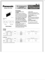
I've been looking at DC SSR's, and think that this one may work with Z's sketch and the SainSmart boards. I know they won't plug straight into the board and I'll have to make a sub-board and patch it in, but just wanted to get your opion before I order 25 of these (only need 16, but like to have spares on hand).

Your thoughts?

image.jpg

Thanks,
Mark
 
Thoughts? That document is a bit skimpy on details, and I didn't get around to finding the full specs on the web.
 
Howdy LightUp,

I've been looking at DC SSR's, and think that this one may work with Z's sketch and the SainSmart boards. I know they won't plug straight into the board and I'll have to make a sub-board and patch it in, but just wanted to get your opion before I order 25 of these (only need 16, but like to have spares on hand).

Your thoughts?

Thanks,
Mark
Basically it should work as a DC SSR.
But ... slapping this DC SSR into an existing sainsmart board may not be as simple. One could buy 1 or 2 SSRs and experiment on the bench, but the datasheet for actual SSR used and the schematic for the actual sainsmart board would be most helpful. Otherwise you are 2nd guessing, (which you are asking me to do,) - which to me is poor engineering. :)

Edit: I did find a pdf datasheet for the AQZ10 but it didn't exactly match your photo.
http://datasheet.octopart.com/AQZ202-Panasonic-datasheet-610584.pdf
OK, I did find a "voltage version" datasheet.
https://www.panasonic-electric-work.../pewnew/ds_x615_en_aqz10d_20d.pdf?type=target
 
Last edited:
Back
Top