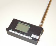
Antenna Mount

That FM Tx works very well. I get several hundred feet with a 30" piece of wire soldered to the "ANT" pad. Originally I taped the wire to the wall so it's vertical, but have since changed to a 2' telescoping whip (looks nicer but less range).

If you prefer going full dipole then the copper area around the ANT pad is the ground plane. You can scratch off the solder resist coating to allow soldering the dipole antenna's counterpoise element. As an alternative, the antenna ground can be connected to power ground.

TLDR; Solder the Dipole to the PCB at the ANT pad and nearby ground.

- Thomas
 

Attachments

  • FM_Tx1_800.jpg
    FM_Tx1_800.jpg
    76.7 KB · Views: 39
Did you 3D print that case? Are there any solutions that already come with the case and antenna?
 
This particular FM transmitter is intended for DiY makers, so there's no ready-to-use option. But in my opinion it's a fantastic performer.

I designed the case and 3D printed it in black ABS. The telescoping antenna is an Amazon item, 2 pcs for $4 total.

Alternatively, you could probably fit it in a Altoids tin. Or one of those little plastic project boxes found on Amazon. Keep in mind that you don't need to see the display or mess with buttons because it remembers all settings when power is removed. So no need to machine the enclosure other than drill a hole for the external wiring.

BTW, the USB audio feature works well. So PC operation is as easy as plugging in a USB cable. And this mode does not not require external power because USB provides the 5VDC.

- Thomas
 
It looks like a nice design but I am working on so many items I am not sure I want to build my own radio transmitter box. I do consider buying a 3D printer, though. Did you buy the design for it from somewhere? If so where and what was the cost for the design?
 
Thanks for the input. This is what makes the forum great! I do like the case design, however, since I don't have a 3-D printer (great gift idea from the wife, I'll have to drop some hints for next year) I do have a project box I'll put it in. Once again thanks for your help.
 
Did you buy the design for it from somewhere? If so where and what was the cost for the design?
The case is my own design, so "cost" was just a couple hours of my time using a CAD program. My printer gets a lot of use and is a nice tool to have on hand.

- Thomas
 
The case is my own design, so "cost" was just a couple hours of my time using a CAD program. My printer gets a lot of use and is a nice tool to have on hand.

- Thomas

Would you mind sharing the design? I am considering buying a printer so I might go this way. Most likely not for this year but next year.
 
Would you mind sharing the design? I am considering buying a printer so I might go this way. Most likely not for this year but next year.

The attached zip file contains the STL files for 3D printing. I suggest re-scaling the print to 101% to account for shrinkage and print with ABS filament.

It is designed for this telescoping antenna: https://www.amazon.com/dp/B08HYK1NPD

Construction Notes:

  1. The antenna is installed using a 4-40 x 1/2" (or M3x12) machine screw and nut. I use a small ring lug with the screw for soldering the antenna wire.
  2. There's a small 4x10mm rectangular cut out on the side of the case for a micro-sized mono/stereo slide switch. I don't have a part number, it was just a random choice from the parts bin.
  3. The PCB can be held in place with a small drop of hot melt glue in the corners. But I use a piece of non-conductive foam that compresses against the board when the cover is installed.
  4. Two M2x8 screws hold the back cover on.

The buttons are recessed, which prevents accidental presses that could change your settings. A pen or pencil tip is a handy tool to press the buttons.

- Thomas
 

Attachments

  • FM_Tx_Case_STL.zip
    67.7 KB · Views: 1
  • FM_Tx_Case1_600.jpg
    FM_Tx_Case1_600.jpg
    60.5 KB · Views: 11
Back
Top