harrison0550
New member
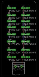
My show runs all 5v so Ive always had a ton of power injection. This year I want to add a power distribution board in each of my PSU enclosures. I know nothing about PCB design but have always wanted to learn. I grabbed eagle and created this........

I really want to add mini blade style fuse holders to each output but reality is if its not in the eagle library I have no idea how to create it.
Like this...
http://www.mouser.com/ProductDetail...byASjpXK1g==&gclid=CN6s6-GHsbwCFWxp7AodxwwAbQ
Would anyone be willing to help me get the fuses in the eagle file and look to see if I'm doing things right?
Attached is the SCH file and BRD file.
Any help would be greatly appreciated.


 not 100% sure its right though). Added the fuses to the schematic and board layout and but ground on the bottom layer and VCC on the top layer. Here is where I am at so far........


