Power Distribution Panel

jbair

Supporting Member
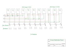
This was my first year of doing a show. I didn't do too much just the eve line, outline windows, not so mega tree, five arches, and a tune to pixel panel. I used separate power supplies and boxes for all of these. I am starting to plan next year's projects. I think instead of having many separate power boxes all located in the same area it will be better to make a large Power Distribution Panel. I have made a drawing of how I think it will need to be wired. I would appreciate for anyone to look at the drawing and make sure it is correct. Yes, its BIG but I am trying to make one and be done. I plan on adding some power-hungry items in the future (3- 4' X 8' panels with 1" spacing etc.).

Thanks for your help.
 

Attachments

  • Power Dist. Panel.jpg
    Power Dist. Panel.jpg
    87.1 KB · Views: 45
I like it and I don't...centralized power is cool and would really simplify life if you just grabbed a connector and plugged it in. But as with all things, there is usually a tradeoff. My take. If you are designing a power distribution, put your HV where you are likely to use it and install appropriate LV where you need it.

Most of your power is 5V. Are most of your props within 15 feet of the panel? If not, beware of voltage drop affecting the props.

Unless you are running 240V to the PSUs, I would add more inputs. 280A at 12V is around 30A at 110V. So one regular circuit won't drive it. You could tell me that you are only going to run 80% and I would still say you are over provisioning the circuit. You could tell me you are only going to do 50% of the 80% and I'd still be leery of a 15A 110V circuit driving it. I think we have many real world examples of people running five 29A 12V PSU off a single 15A. So, in that regard, probably something you could do assuming you keep the load down.

However, you are designing from scratch. You should use max values in the design.

An alternative approach is to use MV (medium volt) supplies and put bucks at the props.
 
I should have drawn it differently, but I will divide the total amperage by three for the input power. 50/3=16.7 Amps each of 20 Amp circuits.

Your correct about the power loss, I didn't think of that. I calculated it and am amazed that my arches are working. They are 12V on 14ga wire but still. I am calculating my power needs for 100% on the lights and sizing the transformers at 150% needed amperage.

Like I said this is my first year and are probably doing a lot of things wrong. Learning as I go. I am also probably paying too much for everything too. Like the wire used to go to the props, what kind of wire should I be using. This is what I have used this year https://www.amazon.com/dp/B096FJTVF5?psc=1&ref=ppx_yo2ov_dt_b_product_details . That gets expensive.

You mentioned MV what voltage are you talking about? Also looking at the bucks they are a low amperage output. Can there be multiples with the negative tied together on a single prop if needed?

I have so many questions and I am grateful for any help you can give me. Would it be ok with you if I were to IM you for help? I don't want to be a bother.

Thanks Again
 
You should keep the conversation here but I don't mind a PM. It is nice here because you are not the only person having this question-you are just the current one asking about it. Of the active voices on the forum, @martinmueller2003 is probably the best at MV to 5V. I think he said 24V with bucks everywhere. He engineers for very few power problems. My props are all 12v with local PSUs.

On the question of your wire. That wire is CCA (copper clad aluminum). Most people on this forum will recommend copper wire. There are pros and cons to CCA. I see this statement on the Amazon link
Advantage of Copper clad aluminum: Here are the facts about CCA vs OFC. CCA wire offers the same signal frequency and reliability in terms of corrosion resistance to copper wire.
From my study, copper wire is better than CCA for most of our uses and we have anecdotal evidence from Christmas light forums that CCA is NOT the same corrosion resistance as copper. I don't know this guy or his biases but just read this page and you will get a feel for some of the reasons I prefer copper. In particular, notice the safety warnings. https://www.truecable.com/blogs/cab...aluminum-vs-copper-fluke-test#page_comments=1 He is talking about cat 5e cable but extrapolate to bigger wire and you get the picture.
 
If I was revisiting mine..... buck converters available online will take up to 40V in. You might want to consider running your circuits at 36V DC then dropping to 5V and 12V near where your pixels are. Keep in mind the power rating of each buck converter. Although this means more hardware, higher voltage (lower current) means you can get away with thinner (cheaper) cable so this approach may actually be more cost-effective. Assuming you're also distributing pixel data, remember your controller's 0V needs to be at the same potential as your PSU's 0v too. I'd put breakers / fuses both at the PSU end and on each of your sub-circuits. There are tricks for getting data over longer cable distances by using null pixels, or by using a differential transceiver on each end.
 
Back
Top