Snowflake Projector Light

So I bought a snowflake projector light from eBay, something like this:
Screenshot 2021-10-03 at 19.06.47.jpg

Overall the effect is good and it's surprisingly bright (total power consumption is IRO 7W)

I thought I'd have a go at make it DMX controllable, via an arduino or similar. The unit has three 'channels' - the motor rotation speed, and two different sized snowflakes with associated LEDs. Interestingly using the remote it's only possible to switch on both snowflake LEDs or neither - but I was thinking it might be possible to generated some interesting effects by having them controllable / dimmable individually.

There's some incredibly devious electronics I'm struggling to get my head around. The unit is 5V DC powered, but there's something clever going on with the LED driving. The motor speed would be an easy win, it just needs a PWM signal from a microprocessor which takes the value of a DMX channel

The LEDs have me stumped though. Connecting the LEDs direct to my 5V bench PSU they pull about 30mA, but via this circuit the consumption is more like 700mA per LED - they are mounted to a heatsink which gets quite warm. I'm thinking the whole board (which is multilayer) is some kind of boost converter, the PCB itself also gets warm (like it is the inductor in the circuit.)
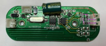
SnowflakeProjector.jpg

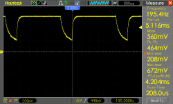
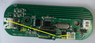
The unit is RF controlled i.e. there is a remote to turn on/off and adjust the motor speed. When powering up it defaults to 'on' so that might help me. There's an onboard 3.3V regulator for both ICs - I believe the IC on the left (unlabelled) is concerned with the RF side of things, it also has the crystal connected. The IC on the right controls the two LEDs - It has an input signal from the other IC, i've shown all 4 output lines in yellow but this unit is the 2 channel version. The yellow lines are a 3.3V 1KHz signal, 1ms low, then 4 ms high (so a duty cycle of 80%). The A09T SMD are p-channel MOSFETS (labelled Q2 and Q5), so my understanding is they are 'ON' for 20% of the time. The 3 pin connector goes to the LED board, top pin (shown in red) is at +5V, The lower 2 pins (shown in purple) are connected to the MOSFET drains via 1 ohm resistors (labelled 1R0). The MOSFET source pins appear to be direct to ground (when testing with a multimeter), but I'm thinking there some additional trickery in place.

I tried removing the MOSFETS and driving via an external circuit (using N-channel with 20% duty cycle i.e. 4ms 'low', 1ms 'high' - but I don't get the crazy over-driven LED thing happening. I'm going to throw the word 'resonance' in as a suggestion?

I have no idea what's happening - I may end up making the motor speed controllable, but just a general on/off control from another channel (maybe 0-128 = off, 129-255 =on). Or perhaps single channel i.e 0 = off, 1-255 =LEDs on , motor slow to fast.

Any thoughts with what is going on with this clever circuit wold be greatly appreciated!
 
Last edited:
I should add I have also probed around the board with my oscilloscope (ref'd to the PSU ground) and I can't find any voltages much above 5V. Hence my utter confusion.
 
What if you drove with with a Bipolar instead? Once you get above threshold voltage, diodes are a function of current. It sounds like there's some LED current driver circuitry I'm missing, but the simple version is just a bipolar. Just inch up the emitter voltage very slowly.
 
Hi Richie, google is telling me that an A09T is an N channel MOSFET which means this would have an 80% on duty cycle. This may explain why you could not over drive this or by much anyway. Any chance of a photo of the LED board.
 
Right you are - yes it's a N-channel MOSFET

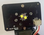
Here's the LED board, I have removed the snowflake 'gobo' which sits on top of these two LEDs. Looks like there was a 4 channel version planned. A little detective work suggests these are CREE LEDs (or similar) the footprint is 3.4mm. From the datasheets I'm thinking these are the 3.3V driven at 700mA. Checking the voltage drop access each LED with a multimeter shows around 2.8V - I'm thinking this is related to the 4/5 duty cycle on the controlling signal. Maybe they did this because the LEDs were getting too hot if run at full power for a long duration? The plate they are mounted to is the heatsink, it gets relatively warm. Also the combined current with both on is about 1.1A, again this is possible due to the pulsed operation (less than the expected 1.4A)
LED.jpg

Here's a better image of the main board, it's tricky to revere engineer since there are multiple layers, also inductors which in some cases I think are the actual tracks. I'm still unclear on if the board is RF or IR controlled - the remote has an LED on the front which actually lights up (so is not IR). I also don't spot a receiver anywhere on the board, plus it works without line-of-sight. Hence my thinking is it's RF.
board.jpg

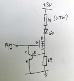
So I'm thinking if I disregard the original board, I need to build two driver circuits. This is my normal 'go to' circuit, I use similar in my garden lighting. The lower resistor sets the current to 700mA, the upper resistor reduces the voltage across the LED from 4.3V (5-0.7) to closer to 3.3 V. I know this isn't without it's faults, is there a better way?
circuit.jpg
 
Last edited:
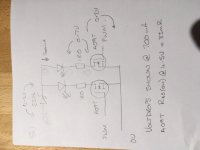
Hi Richie, looking at the original circuit board / LED driver (sketch below).
IMG_1356 (002).JPG
The incoming 5V passes through a SS26 Schotty diode. From figure 2 of the data sheet below for a single LED passing 700mA the volt drop is going to be 0.4V dependant on the temperature.
(https://www.onsemi.com/pdf/datasheet/ss26-d.pdf)

This then splits to pass though the LED board. On returning to the main PCB it passes through a 1R0 resistor. At 700mA the volt drop will be:
V = I * R
V = 0.7A * 1 Ohm
V = 0.7V

This then passes through the A09T (which is a AO3400 data sheet below).
One the first page under ‘Product Summary, it shows an RDS(ON)(at VGS = 4.5V) of <33mOhms.
Which means that the Drain Source resistance is <33mV when the voltage applied between the Gate and Source is 4.5V.
To calculate the volt drop:
V = I * R
V = 0.7A * 0.033 Ohms
V = 0.23V
(http://www.aosmd.com/pdfs/datasheet/ao3400.pdf)

We now know the supply voltage and the volt drops of the components in circuit with the LED and can calculate an estimation of the voltage across the LED.
LED Voltage = Supply voltage – (Schotty diode volt drop + 1R0 resistor volt drop + MOSFET volt drop)
LED Voltage = 5V – (0.4V + 0.7V + 0.2V)
LED Voltage = 5V – 1.3V
LED Voltage = 3.7V
So they could be powering the LED with 3.7V to get the 700mA current.

If that is the case your ‘go to’ looks like it may have too much resistance:
2 x 1R0 dropping 0.7V each at 700mA is already 1.4V drop leaving 3.6V for the LED and then throw in some Drain Source resistance for the MOSFET, lets say this just gives a 0.1V drop and you are now down to 3.5V. That may not be enough to get the full 700mA.

This is all estimation, what you really need is a measurement of the voltage across an LED. This is hard to measure with a meter when PWM is involved it is easier to scope across the LED and because it looks like it might be tricky on the LED board I would scope from the output of the Schotty diode to the input of the 1R0 resistor on the main board.
 
Last edited:
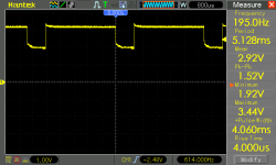
Okay as promised here's the plot across each of the LEDs. I actually connected GND to the large electrolytic cap + terminal, so have inverted the signal to give this.
plot1.png

And for completeness here's the voltage drop across the diode (probed between +5 input) and GND to the large electrolytic cap + terminal
plot2.png

circuit.png
 
Last edited:
So I'm resurrecting this project from a couple of years ago.

The projector has inside it a couple of CREE LEDs, and a motor which runs on about 3.3V quite happily. My plan is now to replace the electronics and interface it to a WS2811 IC, so the three channels will control motor speed, and dimming of led #1 and led #2.

Having blown up the original LEDs through my own ignorance, I sourced a couple of replacements from AliExpress and have installed them (I now have a hot air rework station, these are SMDs). The LEDs i purchased are rated at 3.4V 1500mA each (confirmed on the packaging), so in theory may be more powerful than the original ones. I bought a couple of these driver ICs which claim to be able to drive IRO 30-1500mA, however running from my bench PSU the LED only pulls about 340mA. Does anyone have thoughts on why this is significantly lower than the quoted 1500mA? I have turned the adjustment pot on the board to its maximum.
https://www.aliexpress.com/item/4000321995420.html

The LED is certainly bright at the 340mA, just wondering if I can get any more out of it. I would also need to check the heat dissipation. The two LEDs are surface mounted to an aluminium plate inside the device.

I think interfacing to the WS2811 should be fairly straightforward. The motor is OK to turn in one direction only, and the LED driver boards mentioned above have PWM inputs.
 
I have since found this datasheet for the driver IC, which includes information on setting the sense resistor value
https://www.hestore.hu/prod_getfile.php?id=12002

The resistor shipped on the board has code 102, which I believe means 1K.

The formula shown for the resistor is I = 1800V/R where I is in Amps, or R= 1800V/I
My current (measured on the bench PSU so might be slightly more than is reaching the LED) is about 340mA, so in theory R would be 1800 x 3.4 / 0.340 =18 KOhm

My circuit is essentially the same as that on page 2 of the above document, so a single LED and fixed value resistor (with the pot turned fully one way, it's resistance is zero). The supply voltage is 3.4v.

There's obviously a gap in my understanding somewhere...
 
Last edited:
Is the current saturated at 3.4V? i.e. 3.5V doesn't change anything? Looks like you're supplying it right at the threshold voltage.
 
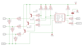
Not specifically related to this project, I came up with this circuit which converts a 12V system running WS2811 data to 3 x logic level signals. The idea of this is I'll use this to replace the microcontroller on the snowdlake projector. I'm not sure yet if I need 3.3V or 5V, but this can be tweaked by adjusting the potential divider ratio on each of the outputs. This circuit also assumes the circult being connected to has hight impedance (like a logic level mosfet). I'm no expert but hopefully this is vaguely on track. Checking on my scope it seems to work...

This circuit inverts the WS2811 PWM, and reduces it from 12V down to the required level.

sxhematic.png

Comments / criticisms welcome
 
Is the current saturated at 3.4V? i.e. 3.5V doesn't change anything? Looks like you're supplying it right at the threshold voltage.

I measured the voltage across the LED and adjusted the PSU until I got the rated 3.4V. I still can't get anywhere near the rated 1500mA through the LED using this driver. I'm not sure what I'm doing wrong.
 
My attention has now turned to another similar product I have purchased (I never made the LEDs adequately bright on the original board). I finally got it open (it uses 2.7mm triangle head screws, so needed to get hold of a bit for that)

This one has 4 x Cree LEDs, controlled in two groups of two, and vs the original unit which uses a normal brushed motor and gearbox, this one is using a stepper motor and driver IC. Correction - the driver IC is a general purpose darlington driver, not specially for stepper motors as such, but commonly used for these small 5 wire motors.

See PCB below - it's double sided and has some additional components on the reverse (capactitors, crystal for Microprocessor, inductor for buck converter). Power is from 6V DC

PCB copy.jpg

I've identified the components as best I can. I have no idea what the DQ069A is, but looks to be the main processor? Perhaps this works in conjunction with the Atmel IC above which houses the 'program'.

My plan is to make it WS2811 controlled (R = LED group 1, G = LED group 2, B = rotation speed), using as few extra components as possible.

The LEDs are straightforward since these are already switched / dimmed by a 5W PWM signal (see pins identified on PCB)- so that could easily be sourced from an external circuit. The stepper motor is going to be more of a challenge (probably not one I can solve!) since it needs 4 x pulse outputs from the Microcontroller. I'm thinking I might be better using the 'normal' motor from the V1 I have, and controlling the speed using PWM? It's a slightly different size so would need some modifications to fit in the case.

When using the stepper as intended, it offers slow, medium and high speeds. The pulse widths are 24ms, 12ms and 6ms respectively.

Another option may be to use a 'fixed' motor speed and use the 3rd channel to simply turn the 6V supply to the unit 'on' if PWM duty cycle is above 50% (channel value >127) - does anyone have any tips on how to do that? When powering up, the motor automatically starts in 'slow' speed.
 
Last edited:
Having dome some more probing/testing on the board, I can confirm the 6V in goes to the stepper motor, but the power to all the ICs is sourced from buck converter IC which takes it down to 4.55V. The XL141 has an 'enable' pin which could be set low to switch the whole unit off. So my question is - are there any good strategies for interfacing a WS2811 pin (one of the three channels) to logic high if pulse width >=50% and logic 0 if <50%? (without resorting to additional microprocessors etc)? Or in simpler terms, does a byte value of 255 give a pulse width of 100% and a byte value of 0 give a pulse width of 0%? I may have this concept inverted thinking about it.

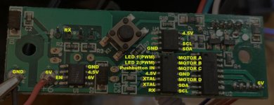
I've also labelled up the main pins on the PCB and their purpose, it's quite nicely built..

PCB2.jpg
 
Last edited:
Back
Top