DIYC Flood
DIYC Flood

Disclaimers
The standard disclaimers pertaining to the information contained on this wiki page are listed here.
What is the DIYC Flood?
The DIYC Flood is a four channel LED based floodlight designed for RGB+W lighting. DIYC Flood makes use of inexpensive piranha style LEDs. The use of temperature compensated constant current LED drivers allows the floodlight to operate across a wide range of temperatures and voltages.
How does the DIYC Flood work?
The DIYC Flood was designed to be used primarily as a RGB+W floodlight. The design allow 4 channels to be switched on/off or dimmed by switching the V- power to ground for the respective channels. It provides a common V+ across all of the channels.
The DIYC Flood was designed to provide a more stable environment for the LEDs by using constant current LED drivers. The Supertex CL2 device provides a constant 20ma thru the LEDs. By using the Supertex CL2 the LED output is maximized while at the same time providing a longer LED lifetime by eliminating the potential to overdrive them due to temperature or voltage variations.
To ensure the best possible color mixing, the LEDs are arranged with the 4 LED colors clustered physically adjacent to each other on the PCB.
Revision History
The v1c version is currently the only version of the DIYC Flood in production.
DIYC Flood (v1c) Parts
In addition to the PCB, you will need the following components:
Mouser
| Mouser BOM | ||
| Mouser PN | Description | Qty |
| 689-CL2N3-G | LED Drivers 90V 20mA Temp Comp | 20 |
| 651-1727078 | Fixed Terminal Blocks 8P 3.81mm 90DEG | 1 |
The terminal blocks are optional, you can solder the wires to the board directly.
Click here for Mouser Direct Project BOM
The CL2 BOM is available from DIYLEDExpress.com
LEDs
The design calls for a total of 60 Piranha Style Super flux LEDs. These LEDs are single color 20ma devices. The DIYC Flood is designed to use 15 Red,15 Green,15 Blue and 15 White LEDs.
| Fall 2011 COOP LEDs | ||||
| Color | Wavelength | Vf | Brightness | 50% Power Angle (deg) |
| Red | 620-635 | 1.9-2.3 | 2000-2500 | 80 |
| Green | 520-530 | 2.9-3.5 | 3500-4000 | 80 |
| Blue | 460-470 | 2.9-3.5 | 1500-2100 | 80 |
| White | 5000-6500K | 3.2-3.4 | 3000-3500 | 120-140 |
The LED Kit is available from DIYLEDExpress.com
Housing
The DIYC Flood needs to be placed in a housing for display. The small design of the pcb allows it to fit in many common waterproof housings. A common Halogen floodlight fixture can be purchased at most hardware stores. A common low cost housing is available from Home Depot. The DIYC Flood PCB is 4.75" x 2.80".
Building the DIYC Flood
The DIYCFlood is a simple device to assemble and test. It is easiest if you build the units by inserting just one color at a time, that way you do not insert the wrong color in the wrong space by accident. Unsoldering the 4 pin LEDs is not easy if you make a mistake.
The board is laid out assuming that the two cathode legs of the LED are towards the top of the board and the two anode legs are towards the constant current drivers on the bottom of the board. This is important because sometimes various manufacturers rotate the package compared to the silkscreen image.
The SuperFlux LEDs have one notched corner on them and they should be aligned with the notched corner on the silkscreen image on the PCB. The location of the various color LEDs are marked by the letters R, G, B and W on the PCB.
Test LEDs
Please note that some of the Red SuperFlux LEDs have opposite polarity from the Green, Blue and White LEDs. These may require rotating the Red LEDs 180 degrees from the silk pattern. To know for sure, always test your LEDs before your solder them to the PCB.
To test the LEDs, you can use an LED tester, which can be purchased on eBay for less than $5; a coin cell battery, such as a CR2032; or a multimeter. To use a coin battery, place the cathode on the negative side and the anode on the positive side. If it does not light up, try it the opposite way. When using a multimeter, put the meter in continuity (Beep) mode and put the negative terminal on the cathode and positive on the anode.
-
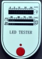
LED Tester
-
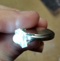
Testing LED with coin battery
-
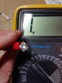
Testing LED with multimeter


Assembly
- Begin by inspecting the PCBs to look for any defects such as cracks or breaks. The holes on the board should be open on both sides. Then inspect and sort out the various parts for the board.
- Insert three Blue LEDs in the right most column of the board closest to the connector in the positions marked “B” on the PCB. Align the notched corner on the LED with the silkscreen. You must solder all four pins.
- Insert one CL2 Constant Current Driver in the B5 position. Align the flat side of the device facing the right side of the board like the silk screen image.
- It is now possible to test the Blue LEDs and the constant current driver by applying 12vdc to the B+ and B- terminals.
- Continue to insert the Blue LEDs in each of the additional columns where the silkscreen is marked “B” moving from right to left
- Insert the CL2 Constant Current drivers in the positions marked B4-B1 as you progress across the board.
- Each column of three Blue LEDs and the Constant Current Driver beneath it complete a circuit. You can test the LEDs as you move across the board by applying power to the B+ and the B- terminals
- After you complete installing the Blue LEDs, begin with the White LEDs.
- Insert three White LEDs in the right most column of the board closest to the connector in the positions marked “W” on the PCB. Align the notched corner on the LED with the silkscreen. You must solder all four pins.
- Insert one CL2 Constant Current Driver in the W5 position. Align the flat side of the device facing the right side of the board like the silk screen image.
- It is now possible to test the White LEDs and the constant current driver by applying 12vdc to the W+ and W- terminals.
- Continue to insert the White LEDs in each of the additional columns where the silkscreen is marked “W” moving from right to left
- Insert the CL2 Constant Current drivers in the positions marked W4-W1 as you progress across the board.
- Each column of three White LEDs and the Constant Current Driver beneath it complete a circuit. You can test the LEDs as you move across the board by applying power to the W+ and the W- terminals
- After you complete installing the White LEDs, begin with the Red LEDs.
- Insert three Red LEDs in the second column from the right of the board closest to the connector in the positions marked “R” on the PCB. Align the notched corner on the LED with the silkscreen. You must solder all four pins. !!NOTE: THE RED LEDs MAY HAVE A DIFFERENT LAYOUT!! TEST BEFORE SOLDERING!!
- Insert one CL2 Constant Current Driver in the R5 position. Align the flat side of the device facing the right side of the board like the silk screen image.
- It is now possible to test the Red LEDs and the constant current driver by applying 12vdc to the R+ and R- terminals.
- Continue to insert the Red LEDs in each of the additional columns where the silkscreen is marked “R” moving from right to left
- Insert the CL2 Constant Current drivers in the positions marked R4-R1 as you progress across the board.
- Each column of three Red LEDs and the Constant Current Driver beneath it complete a circuit. You can test the LEDs as you move across the board by applying power to the R+ and the R- terminals
- After you complete installing the Red LEDs, begin with the Green LEDs.
- Insert three Green LEDs in the second column from the right of the board closest to the connector in the positions marked “G” on the PCB. Align the notched corner on the LED with the silkscreen. You must solder all four pins.
- Insert one CL2 Constant Current Driver in the G5 position. Align the flat side of the device facing the right side of the board like the silk screen image.
- It is now possible to test the Green LEDs and the constant current driver by applying 12vdc to the G+ and G- terminals.
- Continue to insert the Green LEDs in each of the additional columns where the silkscreen is marked “G” moving from right to left
- Insert the CL2 Constant Current drivers in the positions marked G4-G1 as you progress across the board.
- Each column of three Green LEDs and the Constant Current Driver beneath it complete a circuit. You can test the LEDs as you move across the board by applying power to the G+ and the G- terminals
- Install the 8 position terminal block on the right side of the board with the openings for the wires facing the edge of the board. The terminal block is optional, you can solder wires directly to the pads as a lower cost option.


Congratulations! That completes the construction of the DIYC Flood!
Final Testing
TBD
Mounting in Housing
There are numerous ways to attach the DIYC Floods into various housings. Here is an example of two DIYC Floods mounted in one 500W halogen fixture. A common low cost housing is available from Home Depot.

Power Requirements
The DIYC Flood is optimally driven by 15vdc, but it can be driven by 12-24vdc. The design draws approximately 100ma per channel (400ma total). It is not recommended to use 24vdc if you are planning to use these as a full-time ON floodlight. The constant current regulators get pretty warm (about 200degF or 95degC) but are still within spec - but not by much. At 12v constantly on, they run at about 120degF or only just warm to the touch.
When tested with a "typical" lighting sequence (looping - never all off) of single/multiple/all color fades and on/offs at 24.5vdc and again, everything ran just warm.
At 12vdc the LEDs will not be at full brightness, you will need to get to 15vdc or higher to drive the LEDs at full brightness.
Several people have used Laptop Power Supplies to power multiple floods.
Controlling the DIYC Flood
The DIYC Flood requires a DC controller to be connected to it's input for automated lighting. It can be driven by a variety of DC controllers. The Ren4Flood was specifically designed to connect directly to the back of the DIYC Flood in the same housing and provide RENard/DMX control directly at the floodlight. Other DC controllers may be used, examples of these are the Frank's Ren24LV, a Ren64XC with DCSSRs and the Ren48LSD. If you are planing on using multiple DIYC Floods and do not need the added functionality of the Ren4Flood , it may be more cost efficient to use a high channel count controller such as the Ren48LSD to drive the units.
The unit may also be driven without a controller by connecting it directly to a 15vdc power supply and it can then act as a constant floodlight.
The V+ is common for all four colors and the individual colors are controlled by switching the V- to ground.
Schematic
The basic electrical layout of the DIYC Flood is an array of clusters of 3 LEDs connected thru a constant current LED driver. There are 5 clusters of 3 LEDs (15 total LEDs) connected to each of the 4 channels.

PCB
The PCBs for the DIYC Flood were designed by Brian Ullmark (budude). The PCB was designed to allow users to home etch the board. The board is 4.75" x 2.8". The layout can be found here. They are also available from DIYLEDExpress.com


Design Options
Due to the modular nature and the use of constant current LED drivers, users can substitute any color LEDs they would like into each of the channels. In addition to the usual Red,Green,Blue and White, super flux LEDs are also available in Yellow, Purple/UV and Infrared. The DIYC Flood could also be built as a solid color floodlight by filling all positions with a single color.
To reduce the cost, the DIYC flood can be built omitting the terminal block by soldering the power wires directly to the PCB.
To reduce the costs even further, it is possible to substitute a fixed value resistor for the Supertex CL2 constant current device. Users are warned that this may lead to reduced LED lifetime and the need for a stable power supply. Resistor values can be calculated using a LED calculator. Typical Vf for Blue, Green or White LEDs are 2.9-3.3V. Typical Vf for Red LEDs are 1.9-2.3V. Typical Superflux LEDs draw 20ma.
Other Information
DIYC Flood Discussion Threads
Initial Thread
Interest Thread
2011 Group Buy
Video
FAQ
TBD