Fox Cub Ren-W Changes
Fox Cub Ren-W Changes
Please see the standard Disclaimers
More detailed documentation on Fox Cub can be found in the Fox Cub Overview
Overview
Ren-W provides RS232 voltage levels via the MAX232 which is too high for the RS485 voltage levels FoxCub16 uses. Do not use the Ren-W without modification with FoxCub16, the ATMega328p will eventually overheat.
The following details alterations to 2 boards. Board 1 is a Ren-W transmitter connected to FCSquealer. Board 2 is a Ren-W receiver connected to the FoxCub16 RS485 network.
The Max232 chip should be removed on both boards.
http://www.doityourselfchristmas.com/wiki/index.php?title=Ren-W_BOM_and_Construction
Ren-W Transmitter Connected to FCSquealer
The changes to the Ren-W Rev 6 PCB are minor:
- Remove Max232IN chip from Ren-W
- Make sure JP2 is NOT jumpered.
- Remove RJ45 from transmitter board.
- Jumper TX, (RX should be NOT jumpered)
- Connect 3 Wires between the Ren-W Rev6 and FCSquealer:
- JP4 (GND) on the Ren-W to the Ground terminal on the DC Power socket on FCSquealer
- JP3 (5V) on the Ren-W to the 5V terminal on the DC Power socket on FCSquealer
- JP2 (left side, furthest away from the LED) on the RenW to R3 (the end furthest away from the DC Power Socket) on FCSquealer
Note: It's permitted to use the Ren-W and FCSquealer for transmitting both wirelessly and via Cat5E (RS485) at the same time.
Ren-W Receiver connected to RS485
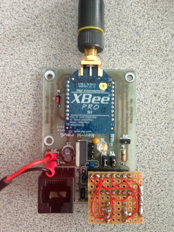
A DS75176 is used as a RS485 transmitter.
- Remove Max232IN on the Ren-W
- Make sure JP2 is NOT jumpered on the Ren-W
- Jumper TX and RX on the Ren-W
- On the Ren-W, solder pins 7/8 on the RJ45 together, and connect to 5V on the board.
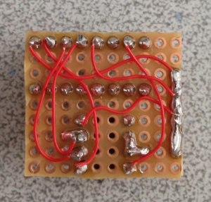
- On the DS75176 connect:
- Pin 2 to Pin 3 and connect that via a 4.7K resistor to 5V
- Pin 4 to Pin 10 on the Max232 pinout (note MAX232 is removed) on the Ren-W
- Pin 5 to 0V
- Pin 6 to Pin 7 with a 120 Ohm resistor
- Pin 8 to 5V
- Also connect Pin 6 to the bottom of the RX header on the Ren-W (bottom is nearest the LED)
- Also connect Pin 7 to the bottom of the TX header on the Ren-W (bottom is nearest the LED)
- Connect Pin 12 on the Max 232 pinout (not MAX232 is removed) on the Ren-W to 5V
- Supply 0V to JP4, supply 5V to JP3
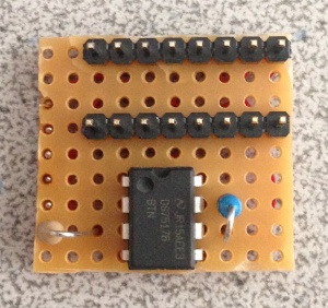
Another way to implement the receiver changes is to create a daughter board that plugs into the MAX232 DIL socket:
Tested Settings For Ren-W, FoxCub16 and Vixen
- XBee Configuration
- Function Set: XBEE PRO 802.15.4 Tested Firmware Version: EC
- Mac Mode: 1-802.15.4 NO ACKS
- Interface Data Rate: 57600
- Parity: No Parity
- Packetization Timeout: 0
- Vixen Configuration
- Baud: 57600
- Parity: None
- Stop Bits: 1
- Data bits: 8
- FoxCub16 Configuration
- Baud: 57600
NOTE: Speeds over 57600 won't work in general with the Ren-W due to XBee Radio limitations


