Power Pops Fanout - 1 Input with 4 Outputs: Difference between revisions
Ukewarrior (talk | contribs) No edit summary |
Ukewarrior (talk | contribs) |
||
| (140 intermediate revisions by the same user not shown) | |||
| Line 1: | Line 1: | ||
==The Pops Power Fanout Board is a simple DC power splitter That has been LOAD Tested with Scientific Equipment.== | |||
==The | |||
< | This board is designed to take one input DC power feed and split it into 4 Main outputs & 4 accessory (low amperage) outlets.<br> | ||
The | The current version is v2.1. | ||
<br> | |||
<br> | <br> | ||
Each Main output on the board has its own mini-automobile style fuse that is rated up to 5 amps.<br> | |||
The four accessory outlets share one mini-automobile style fuse. <br> | |||
Each fuse has a LED status indicator to show if power is flowing through that fuse; therefore showing that power is present and that the fuse is good. | |||
<br> | <br> | ||
<br> | <br> | ||
There is a switch on the board that activates the function of all the status LEDs thereby allowing the user to turn off the LEDs unless needed. This switch does NOT turn off the power feed. It has no affect on the flow of power except to the LED indicators. | |||
<br> | <br> | ||
[[File:Pictureof v2-1.jpg]] | |||
<br> <br> | |||
<p> | |||
== Finished Board == | |||
[[Image:Purgeme2.jpg]] | |||
</p><p> | |||
== General Features == | |||
</p><p> | </p><p> | ||
'''The | '''The Power Pops Fanout board has these main features''' </p><p> | ||
'''1. | '''1. Supports the splitting of up to 20 amps of DC power into 4 individual power outlets of up to 5 amps each.'''</p><p><br> | ||
'''2. | '''2. Has four accessory outlets to power low amperage devices like a voltmeter or a fan.'''</p><p><br> | ||
'''3. | '''3. Is a DIY board using all through hole components for easy DIY soldering.'''</p><p><br> | ||
'''4. Was designed and LOAD TESTED to support up to 20 amps of DC power at a maximum of 28 Volts.''' | |||
<br><br> | <br><br> | ||
''' | '''5. Input & output power can be soldered directly to the board or mounted via Screw down lugs(input) and 5mm terminal blocks(outputs).''' | ||
<br><br> | <br><br> | ||
''' | '''6. Each Main power output is individually fused with a status LED indicating the state of power and the fuse.'''<br><br> | ||
'''7. The four accessory outlets share one Fuse.'''<br><br> | |||
'''8. The board measures 100x50mm'''<br><br> | |||
'''9. Has 4 mounting holes.'''</p><p><br> | |||
The board is professionally manufactured with 1oz copper and the holes are through plated. This makes for easy and more error free soldering.</p><p> | The board is professionally manufactured with 1oz copper(top & bottom) and the holes are through plated. This makes for easy and more error free soldering.</p><p> | ||
== A LOAD TESTED Design == | |||
Full load testing was done with this distribution board to ensure that it could perform within the specified guidelines.<br> | |||
Testing was done with genuine Mean Well power supplies in 5v, 12v, 24v and 36v, LRS-350 series. <br> | |||
Load testing was done with TTi LD300 DC Electronic load equipment at 1a, 2a, 3a, 4a, 5a, 10a, 15a and 20a. <br> | |||
The pdf link below documents the testing that was done using 12awg stranded copper wire for input and 14awg stranded copper wire for output.<br> | |||
[http://doityourselfchristmas.com/forums/attachment.php?attachmentid=38064&d=1510023884 Load Testing Report] | |||
== Order some boards == | |||
You can order your own boards from Holiday Lighting. They are stock bare PCBs, Full DIY kits, and assembled units.<br> | |||
You can find them at: http://holiday.lighting | |||
== Fuses == | |||
[[Image:5_amp_fuse.jpg|right|small]] | |||
. | The board has four independently fused power outputs.<br> | ||
The board is designed to use mini automobile style fuses.<br> | |||
Each main output fuse can be any value up to 5 Amps.<br> | |||
It is recommended that the accessory fuse be set to no more than 1 amp. | |||
== | == Disclaimers == | ||
'''USE the Power Pops Fanout board at Your Own Risk !'''</p> | |||
'''The Power Pops Fanout board has NO warranty expressed or implied''' | |||
<p> | |||
== BOM - Bill of Materials == | |||
The | The BOM contains these parts: | ||
- Two screw down power lugs for power input. The board was designed to use part B12-PCB-S from LugsDirect.com.<br> Link: https://lugsdirect.com/B12-PCB.htm<br> | |||
- Four 5.08mm terminal blocks for power output. These are often referred to as 5mm terminal blocks too.<br> | |||
- Five 1/4W resistors. The value of the resistors depends on the input voltage and LED used. However, a value of 1.2K will work for most LEDs.<br> | |||
- Five indicator 3mm LEDs. Any color can be used. The Forward Voltage and current draw of the LED factor into the resistor value combination.<br> | |||
- Four Fuses, mini Automobile style, any combination with any value up to 5 Amps maximum, for the main power outputs.<br> | |||
- One Fuse, mini Automobile style, with a value up to 1 Amps maximum, for the accessory power outputs.<br> | |||
- Five Fuse Holders, specifically Keystone parts: 3544-2 or 3634-2. Please note that 3634-2 has a mechanism to hold the fuse especially tight. Some folks may find this annoying; therefore, 3544-2 is recommended.<br> | |||
- One SPDT mini switch. eg. digikey part: 450-1609-ND or Sparkfun part: COM-09609 If you look around, you can often find these at other suppliers for much less than digikey or sparkfun. The leads on this switch are spaced at .1" apart or 2.54mm which is the same as your typical pin header strip.<br> | |||
- Four, two pin, pin headers, 2.54mm lead spacing. You can also use a terminal block with 2.54mm lead spacing. | |||
== | == Construction Information == | ||
One specific oddity that may not be obvious is that the fuse holder board pins are not spaced evenly from side to side. Therefore, there is only one correct orientation as shown by the fuse holder outline on the board.<br> | |||
The LEDs have a horizontal line above one of the mounting holes. This is the LED cathode (usually indicated by a flat spot on the side of the LED)<br> | |||
The resistors can go on in any fashion as they are not polarity sensitive. <br> | |||
As noted on the board, the input wires should be 12, 14 or 16 AWG. If using 16 AWG or if using stranded twisted wires, the lug manufacturer recommends the use of wire ferrules.<br> | |||
The only tricky part of assembling the board is the input power lugs as these have a very large surface area to cover. Just take your time and have plenty of solder ready to use. You should put solder on both the top and bottom of the board. Be sure to fill the mounting holes completely.<br>NOTE: be sure the screws are tight before soldering to ensure the lug body is tight against the PCB as you solder.<br> | |||
< | |||
It is suggested you solder the lugs on first, followed by the fuse holders, output terminal blocks, pin headers, resistors, the switch, and finally the LEDs. | |||
== Board Layout Diagrams == | |||
The pdf linked below shows the hole layout dimensions.<br> | |||
The outer dimenstion of the board is exactly 100mm x 50mm.<br> | |||
[[Media:Power_board_hole_layout.pdf]] | |||
<br> <br> | |||
The pdf linked below can be opened and printed for a drilling template. | |||
Be sure to print it without any scaling. i.e. print at 1:1 by turning OFF the FIT TO PAGE or SCALE option which by default is turned on. | |||
[[Media:Power_board_layout.pdf]] | |||
== End User Pictures == | |||
Here is '''Kev7274''' testing out the placement of voltmeters on one of his boards: (the alligator clips are just for testing) | |||
[[File:Kev7274.jpg]] | |||
<br> <br> | |||
'''pmiller''' mounted a voltmeter with through hole screws. | |||
He could do this because the top half of the board is the positive power plane, both top and bottom.<br> As long as you don't get into the traces for the low amperage connectors, this will work...and Bob's your Uncle! | |||
[[File:Purgemex.jpg]]<br><br> | |||
Braveit1 created a custom mounting plate for 3D printing and added a voltmeter to his board.<br> | |||
Here the link to the board. It fits harbor freight ammo cans: [https://www.thingiverse.com/thing:3929289 3D print file]<br> | |||
[[File:Distroboard.png]] | |||
Latest revision as of 01:06, 11 November 2021
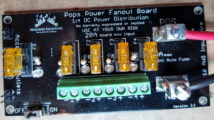
The Pops Power Fanout Board is a simple DC power splitter That has been LOAD Tested with Scientific Equipment.
This board is designed to take one input DC power feed and split it into 4 Main outputs & 4 accessory (low amperage) outlets.
The current version is v2.1.
Each Main output on the board has its own mini-automobile style fuse that is rated up to 5 amps.
The four accessory outlets share one mini-automobile style fuse.
Each fuse has a LED status indicator to show if power is flowing through that fuse; therefore showing that power is present and that the fuse is good.
There is a switch on the board that activates the function of all the status LEDs thereby allowing the user to turn off the LEDs unless needed. This switch does NOT turn off the power feed. It has no affect on the flow of power except to the LED indicators.
Finished Board
General Features
The Power Pops Fanout board has these main features
1. Supports the splitting of up to 20 amps of DC power into 4 individual power outlets of up to 5 amps each.
2. Has four accessory outlets to power low amperage devices like a voltmeter or a fan.
3. Is a DIY board using all through hole components for easy DIY soldering.
4. Was designed and LOAD TESTED to support up to 20 amps of DC power at a maximum of 28 Volts.
5. Input & output power can be soldered directly to the board or mounted via Screw down lugs(input) and 5mm terminal blocks(outputs).
6. Each Main power output is individually fused with a status LED indicating the state of power and the fuse.
7. The four accessory outlets share one Fuse.
8. The board measures 100x50mm
9. Has 4 mounting holes.
The board is professionally manufactured with 1oz copper(top & bottom) and the holes are through plated. This makes for easy and more error free soldering.
A LOAD TESTED Design
Full load testing was done with this distribution board to ensure that it could perform within the specified guidelines.
Testing was done with genuine Mean Well power supplies in 5v, 12v, 24v and 36v, LRS-350 series.
Load testing was done with TTi LD300 DC Electronic load equipment at 1a, 2a, 3a, 4a, 5a, 10a, 15a and 20a.
The pdf link below documents the testing that was done using 12awg stranded copper wire for input and 14awg stranded copper wire for output.
Order some boards
You can order your own boards from Holiday Lighting. They are stock bare PCBs, Full DIY kits, and assembled units.
You can find them at: http://holiday.lighting
Fuses
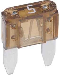
The board has four independently fused power outputs.
The board is designed to use mini automobile style fuses.
Each main output fuse can be any value up to 5 Amps.
It is recommended that the accessory fuse be set to no more than 1 amp.
Disclaimers
USE the Power Pops Fanout board at Your Own Risk !
The Power Pops Fanout board has NO warranty expressed or implied
BOM - Bill of Materials
The BOM contains these parts:
- Two screw down power lugs for power input. The board was designed to use part B12-PCB-S from LugsDirect.com.
Link: https://lugsdirect.com/B12-PCB.htm
- Four 5.08mm terminal blocks for power output. These are often referred to as 5mm terminal blocks too.
- Five 1/4W resistors. The value of the resistors depends on the input voltage and LED used. However, a value of 1.2K will work for most LEDs.
- Five indicator 3mm LEDs. Any color can be used. The Forward Voltage and current draw of the LED factor into the resistor value combination.
- Four Fuses, mini Automobile style, any combination with any value up to 5 Amps maximum, for the main power outputs.
- One Fuse, mini Automobile style, with a value up to 1 Amps maximum, for the accessory power outputs.
- Five Fuse Holders, specifically Keystone parts: 3544-2 or 3634-2. Please note that 3634-2 has a mechanism to hold the fuse especially tight. Some folks may find this annoying; therefore, 3544-2 is recommended.
- One SPDT mini switch. eg. digikey part: 450-1609-ND or Sparkfun part: COM-09609 If you look around, you can often find these at other suppliers for much less than digikey or sparkfun. The leads on this switch are spaced at .1" apart or 2.54mm which is the same as your typical pin header strip.
- Four, two pin, pin headers, 2.54mm lead spacing. You can also use a terminal block with 2.54mm lead spacing.
Construction Information
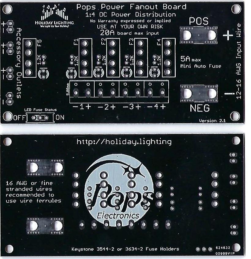
One specific oddity that may not be obvious is that the fuse holder board pins are not spaced evenly from side to side. Therefore, there is only one correct orientation as shown by the fuse holder outline on the board.
The LEDs have a horizontal line above one of the mounting holes. This is the LED cathode (usually indicated by a flat spot on the side of the LED)
The resistors can go on in any fashion as they are not polarity sensitive.
As noted on the board, the input wires should be 12, 14 or 16 AWG. If using 16 AWG or if using stranded twisted wires, the lug manufacturer recommends the use of wire ferrules.
The only tricky part of assembling the board is the input power lugs as these have a very large surface area to cover. Just take your time and have plenty of solder ready to use. You should put solder on both the top and bottom of the board. Be sure to fill the mounting holes completely.
NOTE: be sure the screws are tight before soldering to ensure the lug body is tight against the PCB as you solder.
It is suggested you solder the lugs on first, followed by the fuse holders, output terminal blocks, pin headers, resistors, the switch, and finally the LEDs.
Board Layout Diagrams
The pdf linked below shows the hole layout dimensions.
The outer dimenstion of the board is exactly 100mm x 50mm.
Media:Power_board_hole_layout.pdf
The pdf linked below can be opened and printed for a drilling template. Be sure to print it without any scaling. i.e. print at 1:1 by turning OFF the FIT TO PAGE or SCALE option which by default is turned on.
End User Pictures
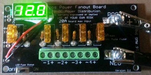
Here is Kev7274 testing out the placement of voltmeters on one of his boards: (the alligator clips are just for testing)
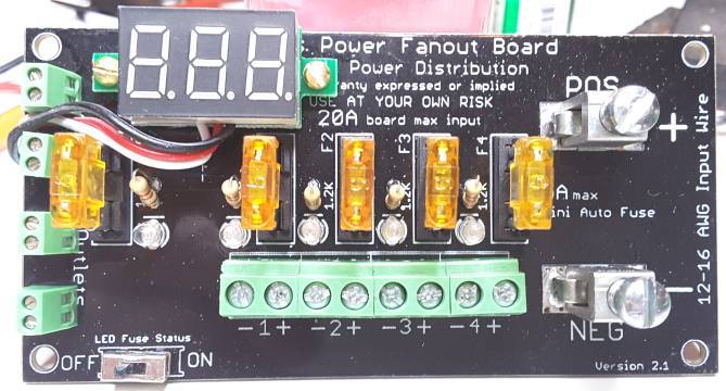
pmiller mounted a voltmeter with through hole screws.
He could do this because the top half of the board is the positive power plane, both top and bottom.
As long as you don't get into the traces for the low amperage connectors, this will work...and Bob's your Uncle!
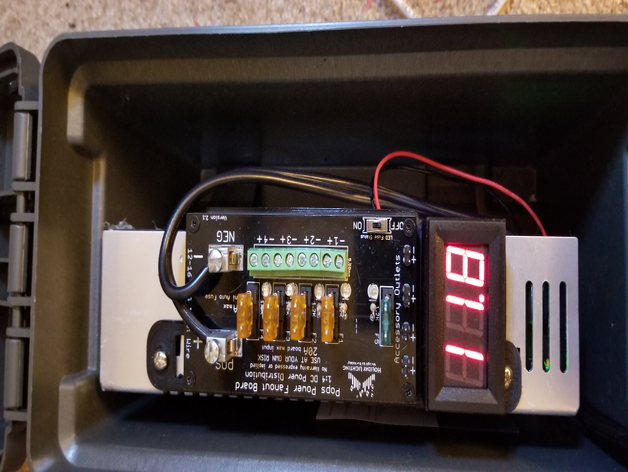
Braveit1 created a custom mounting plate for 3D printing and added a voltmeter to his board.
Here the link to the board. It fits harbor freight ammo cans: 3D print file
