All In One Tester
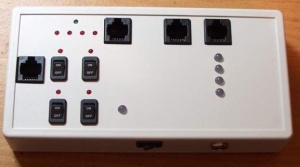
A video showing the functions of the AIOT.
http://media.putfile.com/All-In-One-Tester
The usual disclaimer... If you use any of the information provided here, you do so at your own risk. If bad things happen from using this information, it is 100% your liability.
Now let's build a tester.
This tester will check Cat5 cables for crossed pairs and continuity, tests SSR's, and 595's and Renards for output. A note on testing output of Renards. I have used it with the 8 channel Renard and it works. The LEDs burn very dimmly, but they do light up. Any input on how the output tester works with other Renard boards would be appreciated. Most of the pictures can be clicked for a larger picture.
The PCB is pretty straight forward, and the traces are not real close to each other for an easy home etch. I put three copies of the file on a page to save on transfer paper. The trace file in .pdf can be downloaded here. The Mobile unit trace file is here. Be sure when you print it, that it does not get scaled or the board components will not fit the enclosure.
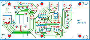
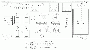
The Parts
I have the parts list as an Excel speadsheet. I also put together a BOM for use with Mouser's BOM import tool. I have two part#'s for the pcb spacers and switches, as there are two different ones that will work. The spacers, one is a 4-40 threaded stand off, the other is just a spacer. Either will work, but I used the threaded ones. The switches are the same other than one has 'On/Off" on the rocker and the other is blank. When you import the BOM, make sure to delete the ones you do not want to use. I have a 8 pin header in the list, simply because Mouser does not have the 6 pin in stock and don't know if they ever will. They are break away style, so just cut off the two extra. I did not put the DC jack on the parts list as it is optional. I used one from Radio Shack (part# 274-1583) If you choose not to add the DC jack, you do not need one of the two pin connectors. You can just solder the battery pigtail to the board. I recommend that you drill two holes in the board to feed the wires up through the board then into the trace holes. This will act as a strain relief. The parts list and BOM include the parts for the Mobile unit also.
Assembly
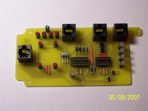
After the board has been etched, it needs to be cut to the profile trace so it will fit into the enclosure. The mounting holes should be drilled 1/8".
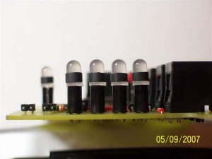
A few things on assembly. The LED spacers..... The long ones are for the small LEDs, and the short ones are for the large LEDs. When inserting the small LEDs, make sure they are fully seated into the recess of the spacer. The large LEDs will just rest on top of the spacer. With all of the LEDs, the short lead goes into the square pad. When soldering the LEDs, it is very important that they are straight in line and perpendicular to the board so they will line up with the holes in the case.
The headers and connectors.....The two pin connectors have a 'locking ramp' on them, this will need to be removed. I used a razor blade. (I was going to use the SL series two pin connectors to keep things matched, but just one cost more than both of the KK series connectors.) When soldering the headers, I inserted them into the connectors to hold them at the right height.
This is optional, Some heat shrink on the large LEDs will cut down on the light from one 'bleeding' over to the one beside it. Cut the tubing 3/32" and just slip it over the LED, no need to shrink it. If these are too long, the enclosure will not want to go together. This is not needed for the small LEDs nor the mobile unit's LEDs.
Switches and stuff
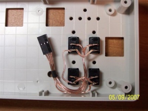
Wiring for the switches need to be routed to stay clear of the LEDs. I used 24ga speaker wire, which fit the crimp terminals well. Cut two pieces 4" long and three more 3" long. A small piece of heat shrink will keep things managable. Wire the switches with the same order that your SSRs are wired. Wire one side of the four switches together and this goes to the 'COM' lead. The channels for the connector are on the 'parts placement' picture. These switches don't like a lot of heat applied to them, so be quick about soldering them.
Power
Power for the board is a 9V battery and an 'optional' DC jack. If you choose to use a DC jack make sure it has a NC switch and is wired properly. If you use the one I listed in the parts section, the + side of the header connector and the + side of the battery wire to the center pin. The - side of the battery to one of the shell tabs, and the - side of the header connector to the other shell tab.
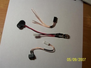
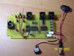
Never exceed 9v when using the DC jack , you could damage your Tester and SSR's if you do.
.
The Enclosure
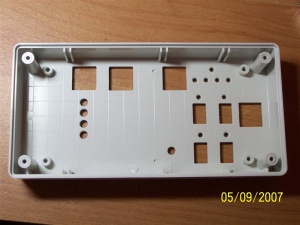
Download this cutout pattern and cut it on the line. This will fit into the recess on top of the enclosure. (picture shows the underside. Place pattern on top) Note the center bosses measurements and set the pattern accordingly. After you are done with the holes, you will need to remove these two center bosses.
Drill the large LEDs holes with a #8 drill bit.(if you do not have one then a 13/64 will do, it's .004 bigger though) Drill the small LED holes with a #32 drill bit.
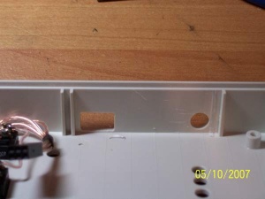
The power switch and DC jacks must be placed as close to the top as possible, and place them like in the picture in relation to the verticle PCB slots. Keep in mind if you use a DC jack that the body will be bigger than the hole, so account for it. The holes for the switches and RJ45's can be done various ways, A dremel tool with a 1/16 drill bit will work, or drill a hole and razor blade the rest out, are a couple ways. If you have access to a CNC, the DXF files for the tester and mobile unit holes, PCB holes, along with the PCB profile cut files can be downloaded here.
The cutout pattern for the Mobile unit is here. Print it and cut it out along the line and place it on the inside of the enclosure lid.
Finishing Touches
Now we can install the switches and DC jack. Find a piece of foam 3/8" thick for a battery pad. A couple dabs of hot glue, or double sided tape works well to hold it place. If you used the 4-40 PCB stand offs, you will need five 1/4" 4-40 screws. I couldn't find them that short, so I cut some down. I used a 4-40 tap to thread the bosses, then ran a 4-40 screw into them to finish out the threads to the bottom. The stand offs have to be seated with the bosses when screwed in. Plug in the connectors. The wires will need formed a bit to clear things and fit well.
After it is assembled, use a known good patch cable and check it's operation.