LEDancer: Difference between revisions
Phil Short (talk | contribs) |
|||
| (54 intermediate revisions by 3 users not shown) | |||
| Line 1: | Line 1: | ||
==General== | ==General== | ||
The LEDancer (Le Dancer) is an inexpensive controller for up to 56 LEDs with a DMX512 input interface. The LEDs are connected together in a Charlie-Plexed common- | The LEDancer (Le Dancer) is an inexpensive controller for up to 56 LEDs with a DMX512 input interface. The LEDs are connected together in a [http://en.wikipedia.org/wiki/Charlieplexing Charlie-Plexed] common-anode configuration. The design needs to use 2N3904 booster transistors for the LED anodes to ensure that the low-level drive of the PIC is not exceeded, a configuration sometimes called [http://www.edn.com/article/470236-_Chipiplexing_efficiently_drives_multiple_LEDs_using_few_microcontroller_ports.php chipi-plexing]. The [[DMX|DMX]] address of the controller can be changed by shunting one of the PIC pins to ground and then sending a specially formatted [[DMX|DMX]] packet with the desires address. | ||
==Disclaimers== | |||
The standard disclaimers pertaining to the information contained on this wiki page are listed [[Disclaimers | here.]]<br/> | |||
==PCB Schematic== | ==PCB Schematic== | ||
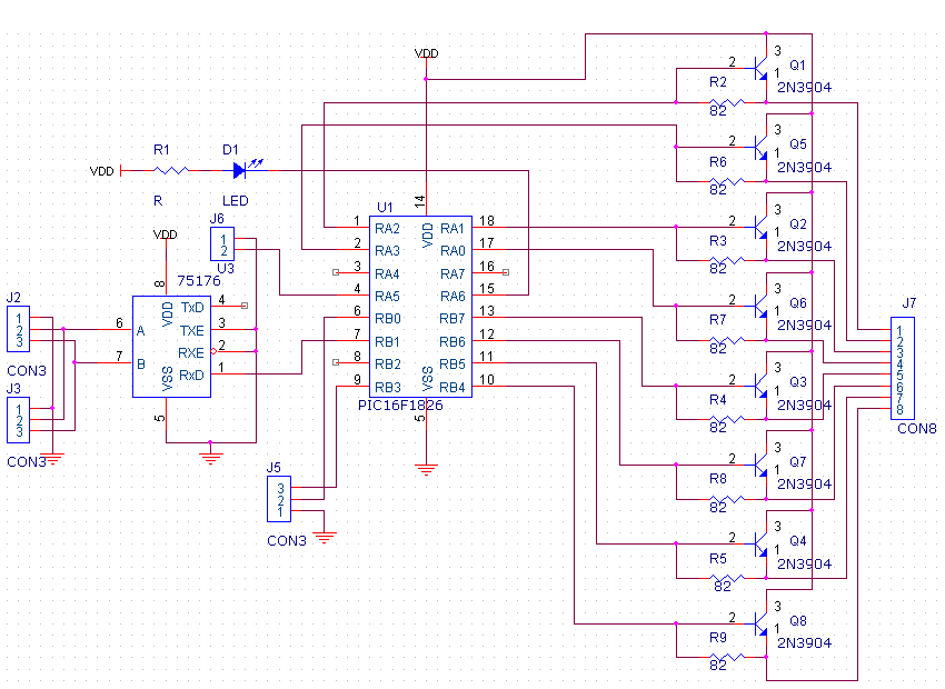
This is a generic LEDancer schematic, useful as the basis of a PCB design. Some of the necessary details (such as a DC regulator) have been omitted from the schematic, but should be included in most PCB designs. | This is a generic LEDancer schematic, useful as the basis of a PCB design. Some of the necessary details (such as a DC regulator) have been omitted from the schematic, but should be included in most PCB designs. | ||
[[File: | [[File:LEDancer2.PNG]] | ||
==PCB Design== | ==PCB Design== | ||
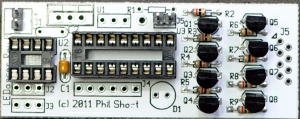
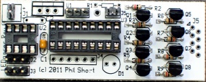
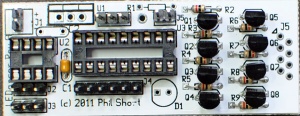
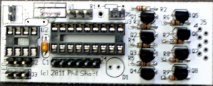
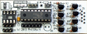
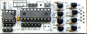
The design consists of a controller board with a [http://ww1.microchip.com/downloads/en/DeviceDoc/41391B.pdf PIC16F1826] and a [http://www.st.com/internet/com/TECHNICAL_RESOURCES/TECHNICAL_LITERATURE/DATASHEET/CD00002183.pdf ST485] RS485 receiver, a jumper for enabling the [[LEDancer#Programming_the_DMX_Address|DMX Address Program Mode]], eight resistors and 8 [http://www.fairchildsemi.com/ds/2N/2N3904.pdf 2N3904] transistors, and some connectors.<br/> | |||
[[File:Ledancer.jpg|300px]] | |||
===Connector Pinout=== | ===Connector Pinout=== | ||
====J1-Power==== | |||
J1 is the 2 pin header located at the top left side of the PCB. The LEDancer can be powered by 5-24VDC. If you are using 5VDC, omit the voltage regulator and jumper the voltage regulator position by soldering a wire jumper to where the two outer pins of the regular would have gone in position U1 near the top left side of the PCB. If you are feeding greater than 5VDC, then you must use the on board voltage regulator.<br/> | |||
Round Hole closest to the top of the board: Positive Power feed<br/> | |||
Square Hole: Negative Power feed<br/> | |||
====J2 and J3-DMX Input and Output==== | |||
The two 3 pin jumpers J2&J3 near the bottom left side of the board are used to bring DMX signals to and from the board. The 3 pin connectors are polarized and should be connected as follows:<br/> | |||
Pin 1 is the Square hole of the three holes on the side towards the center of the board: Connect to DMX Ground<br/> | |||
Pin 2 is the center hole of the three holes: Connect it to DMX Data -<br/> | |||
Pin 3 is the left most hole of the three holes: Connect it to DMX Data +<br/> | |||
Note that the two 3pin DMX connections are setup as a thru connection and can be used as either the input or output of the board. If the LEDancer is the last connection on a DMX data line, it may be necessary to add a 120 ohm terminating resistor to the unused DMX terminals between PIN 2 and Pin 3.<br/> | |||
====J4-ICSP Programming Header==== | |||
J4 is the 6 pin header located in the bottom center of the board. J4 allows the PIC microprocessor to be programmed in place on the board by directly connecting a [http://www.microchip.com/stellent/idcplg?IdcService=SS_GET_PAGE&nodeId=1406&dDocName=en023805 PICKIT2] or [http://www.microchip.com/stellent/idcplg?IdcService=SS_GET_PAGE&nodeId=1406&dDocName=en538340 PICKIT3] programer.<br/> | |||
Pin 1 is the square hole towards the right side of the board closest to D1.<br/> | |||
====J5 (2 pin)- DMX Address Programming Jumper==== | |||
J5 is located in the top center of the PCB. By default the LEDancer is initially programmed to DMX address 1 by the firmware. The address may be changed in the device by either modifying the firmware or by using the special programming instructions [[LEDancer#Programming_the_DMX_Address|listed below. ]] You must temporarily install a shorting jumper across the two pins of J5 to use the special address setting packets.<br/> | |||
====J5(8 pin)- Output to LEDs==== | |||
J5 is located along the right edge of the board and is a 8 pin connector used to connect to the LED Segment PCB. Pin1 of the connector is marked by the arrow next to it on the silkscreen.<br/> | |||
===Jumper Identification=== | ===Jumper Identification=== | ||
J1-Power<br/> | |||
J2-DMX<br/> | |||
J3-DMX<br/> | |||
J4-ICSP Programming Header<br/> | |||
J5 (2 pin)- DMX Address Programming<br/> | |||
J5(8 Pin)- Output to LEDs<br/> | |||
Unumbered 3 Pin- ???<br/> | |||
==BOM - Bill Of Materials== | |||
To build LEDancer you will need parts from Mouser, LEDs, a LEDancer Controller PCB and LED Segment PCBs.<br/> | |||
===Mouser=== | |||
<table border="1"> | |||
<tr><td>Mouser PN</td><td>Description</td><td>Qty</td><td>Optional</td></tr> | |||
<tr><td>538-22-03-2021</td><td>Headers & Wire Housings VERT PCB HDR 2P TIN PLATING</td><td>2</td><td></td></tr> | |||
<tr><td>538-22-03-2061</td><td>Headers & Wire Housings VERT PCB HDR 6P TIN PLATING</td><td>1</td><td></td></tr> | |||
<tr><td>538-22-03-2031</td><td>Headers & Wire Housings VERT PCB HDR 3P TIN PLATING</td><td>3</td><td></td></tr> | |||
<tr><td>80-C322C104K5R</td><td>Multilayer Ceramic Capacitors (MLCC) - Leaded 50volts 0.1uF 10% X7R</td><td>1</td><td></td></tr> | |||
<tr><td>80-C322C334M5U5CA</td><td>Multilayer Ceramic Capacitors (MLCC) - Leaded 50volts 0.33uF 20% Z5U</td><td>1</td><td>****</td></tr> | |||
<tr><td>299-82-RC</td><td>Carbon Film Resistors - Through Hole 82ohms 5%</td><td>8</td><td></td></tr> | |||
<tr><td>512-2N3904TA</td><td>Transistors Bipolar (BJT) NPN Transistor General Purpose</td><td>8</td><td></td></tr> | |||
<tr><td>511-ST485BN</td><td>Buffers & Line Drivers Hi-Spd Lo Pwr Trans</td><td>1</td><td></td></tr> | |||
<tr><td>579-PIC16F1826-I/P</td><td>Microcontrollers (MCU) 3.5KB Flash 256 byte 32 MHz Int. Osc</td><td>1</td><td></td></tr> | |||
<tr><td>571-1-390261-2</td><td>IC & Component Sockets 8P ECONOMY TIN</td><td>1</td><td></td></tr> | |||
<tr><td>571-1-390261-5</td><td>IC & Component Sockets 18P ECONOMY TIN</td><td>1</td><td></td></tr> | |||
<tr><td>604-WP7104GT</td><td>Standard LED - Through Hole GREEN TRANSPARENT</td><td>1</td><td>****</td></tr> | |||
<tr><td>299-330-RC</td><td>Carbon Film Resistors - Through Hole 330ohms 5%</td><td>1</td><td>****</td></tr> | |||
<tr><td>TBD</td><td>5V Voltage Regulator</td><td>1</td><td>****</td></tr> | |||
<tr><td>151-8000-E</td><td>Headers & Wire Housings MINI JUMPER GF 6.0MM OPEN TYPE BLACK</td><td>1</td><td>****</td></tr> | |||
<tr><td>291-120-RC</td><td>Carbon Film Resistors - Through Hole 120ohms 0.05</td><td>1</td><td>****</td></tr> | |||
</table><br/> | |||
===LEDs=== | |||
In addition, you will need up to 56 White Piranha Style Super flux LEDs. Other colors could be used, but you may need to adjust the resistor values on the controller board. <br/> | |||
===LEDancer Controller PCB=== | |||
[[File:Ledancer.jpg|400px]]<br/> | |||
Each LEDancer Controller is capable of controlling up to 56 LEDs connected to it's output.<br/> | |||
The PCB can be found at [http://www.diyledexpress.com/index.php?main_page=product_info&cPath=15&products_id=91 DIYLEDExpress.com] | |||
===LED Segment PCBs=== | |||
[[File:FAST-Segment-PCB1.jpg|600px]]<br/> | |||
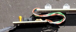
The original LED Segment board is an approximately 6" long modular board that contains 7 Piranha Style Superflux LEDs connected in a [http://en.wikipedia.org/wiki/Charlieplexing Charlieplexed] fashion. The boards are designed to allow multiple boards to be daisy chained to allow various length tubes to be constructed. From 1 - 8 boards can be connected to each LEDancer controller creating a 6" to 48" long display tube.<br/> | |||
[[File:14ledstrip.jpg|1000px]]<br/> | |||
The current LED Segment board is an approximately 12" long modular board that contains 14 Piranha Style Superflux LEDs connected in a [http://en.wikipedia.org/wiki/Charlieplexing Charlieplexed] fashion. The boards are designed to allow multiple boards to be daisy chained to allow various length tubes to be constructed. From 1 - 4 boards can be connected to each LEDancer controller creating a 12" to 48" long display tube. | |||
The LED Segment PCBs can be found at [http://www.diyledexpress.com/index.php?main_page=product_info&cPath=15&products_id=75 DIYLEDExpress.com] | |||
==LED Connections== | ==LED Connections== | ||
THIS SECTION IS OUT OF DATE. | |||
The LEDs can either be hand-wired on some sort of substrate (perhaps some plexiglass or linoleum), or a PCB can be designed to hold the LEDs. In all of the following diagrams LED1 is the LED controlled by the lowest DMX address, LED2 is next, and so forth. LED56 is the LED controlled by the highest (56'th) DMX address. | |||
[ | ===Schematic=== | ||
[[File:LEDancer_LED_SCH.png]] | |||
===Wirelist=== | |||
Output1,LED1-C,LED2-C,LED3-C LED4-C,LED5-C,LED6-C,LED7-C,LED14-A,LED20-A,LED26-A,LED32-A,LED38-A,LED44-A,LED50-A | Output1,LED1-C,LED2-C,LED3-C LED4-C,LED5-C,LED6-C,LED7-C,LED14-A,LED20-A,LED26-A,LED32-A,LED38-A,LED44-A,LED50-A | ||
| Line 44: | Line 116: | ||
Output8,LED7-A,LED13-A,LED19-A,LED25-A,LED31-A,LED37-A,LED43-A,LED50-C,LED51-C,LED52-C,LED53-C,LED54-C,LED55-C,LED56-C | Output8,LED7-A,LED13-A,LED19-A,LED25-A,LED31-A,LED37-A,LED43-A,LED50-C,LED51-C,LED52-C,LED53-C,LED54-C,LED55-C,LED56-C | ||
==Stackable LED Board Design== | ===Stackable LED Board Design=== | ||
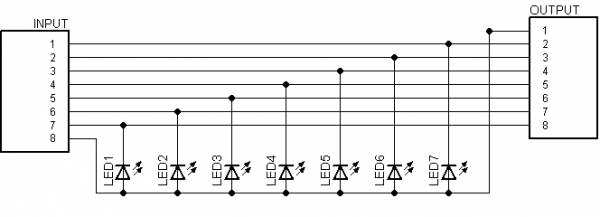
Here is the schematic for a practical stackable board design. By connecting eight of these boards together (output to input, pin-1 to pin-1, etc) the previous schematic/wirelist can be readily built. | Here is the schematic for a practical stackable board design. By connecting eight of these boards together (output to input, pin-1 to pin-1, etc) the previous schematic/wirelist can be readily built. | ||
[[File: | 7 LED Segment Board<br/> | ||
[[File:7ledschematic.png|600px]]<br/> | |||
14 LED Segment Board<br/> | |||
[[File:14ledschematic.png|600px]]<br/> | |||
==Assembly Instructions== | |||
Assembly of the LEDancer is done in three steps: | |||
# Assembly of the LEDancer Controller. | |||
# Assembly of the LED Segments. | |||
# Connecting the two units together and installing them in a housing. <br/> | |||
Begin by inspecting the PCBs to look for any defects such as cracks or breaks. The holes on the board should be open on both sides. Then inspect and sort out the various parts for the boards.<br/> | |||
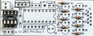
[[File:Ledancer_assembly_01.jpg|300px]] | |||
===LEDancer Controller Assembly=== | |||
#Install resistors | |||
##Solder one 330 ohm resistor in R1 on top center of the PCB. The resistor is not polarized and can go either way. '''The 330 ohm resistor is optional and is only needed if you are installing the green LED on the controller board.''' | |||
## Solder eight 82 ohm resistors in R2-R9 on the right side of the PCB. The resistors are not polarized and can go either way. | |||
##:[[File:Ledancer_assembly_02.jpg|300px]] | |||
#Install IC sockets | |||
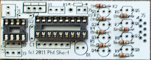
##Solder one 8 pin IC socket on the left side of the PCB at U2. Install the socket with the notch facing to the right side of the PCB, matching the silkscreen. | |||
##:[[File:Ledancer_assembly_03.jpg|300px]] | |||
##Solder one 18 pin IC socket on the left side of the PCB at U3. Install the socket with the notch facing to the right side of the PCB, matching the silkscreen. | |||
##:[[File:Ledancer_assembly_04.jpg|300px]] | |||
#Install capacitors | |||
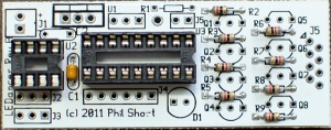
##Solder one 0.1uf capacitor (marked 104)in C1 on the center left side of the PCB. The capacitor is not polarized and can go either way. | |||
##:[[File:Ledancer_assembly_05.jpg|300px]] | |||
##Solder one 0.33uf capacitor (marked 334)in C2 on the top left side of the PCB. The capacitor is not polarized and can go either way.'''The 0.33uf capacitor is optional and is only needed if the voltage regulator is installed.''' | |||
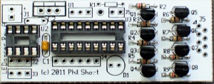
#Solder the eight 2N3904 transistors in Q1-Q8 on the right hand side of the PCB. The transistors are mounted with the flat side facing the top of the board matching the layout on the silkscreen. | |||
#:[[File:Ledancer_assembly_06.jpg|300px]] | |||
#Solder the green LED in D1 in the bottom center of the PCB. The LED is polarized and the long lead goes to the right side of the PCB.'''The green LED is optional and is currently not used by the firmware.''' | |||
#Install the headers. The short end of the header is soldered into the PCB. | |||
##Solder two 2 pin headers in J1 on the top left of the PCB and J5 in the top center of the PCB. '''Header J1 is optional, you may choose to solder your power wires directly to the board.''' | |||
##:[[File:Ledancer_assembly_07.jpg|300px]] | |||
## Solder three 3pin headers in J2 and J3 on the bottom left of the PCB and in the unmarked 3 position location in the top center of the PCB underneath where the silkscreen says U1 and R1. '''Headers J2 and J3 is optional, you may choose to solder your DMX Signal wires directly to the board.''' | |||
##:[[File:Ledancer_assembly_08.jpg|300px]] | |||
## Solder one 6 pin header J4 in the bottom center of the PCB. | |||
##:[[File:Ledancer_assembly_09.jpg|300px]] | |||
#Solder the voltage regulator in U1 on the top left side of the PCB. The voltage regulator is polarized and the heatsink side faces the top of the board.'''The voltage regulator is optional and is only needed if the power to the LEDancer is greater then 5V. If the LEDancer is powered by a regulated 5VDC power supply, you must omit the voltage regulator and install a wire jumper between the two outer pins of where the voltage regulator would go. ''' | |||
#:[[File:Ledancer_assembly_10.jpg|300px]] | |||
#Install ICs | |||
## Install the 18 pin PIC in U3 in the center of the board. The notch on the IC faces towards the right side of the board matching the silkscreen. | |||
##:[[File:Ledancer_assembly_11.jpg|300px]] | |||
## Install the 8 pin RS485 chip in U2 on the left side of the PCB. The notch on the IC faces towards the right side of the board matching the silkscreen. | |||
##:[[File:Ledancer_assembly_12.jpg|300px]] | |||
===LED Segment Board Assembly=== | |||
It is strongly recommended that you test each LED before you solder it to the PCB using a LED tester. LED testers can be purchased on Ebay for less than $5.<br/> | |||
[[File:Ledtester.jpg|100px]]<br/> | |||
Based on how long you are making the LEDancer, you will need to assemble 1-4 LED Segment boards.<br/> | |||
1. Solder the fourteen Superflux LEDs to the LED Segment PCB. The LEDs are polarized, there is one corner that is cut off and not square. The LED must be installed so that the orientation of the notched corner matches the silkscreen. If you are using the LEDs sold in the Fall2011 group buy, they are inserted with the notched corner matching the silkscreen. '''WARNING, Some LEDs from other vendors may have different orientations and they may need to be rotated 180 degrees from the silkscreen drawing. Please check to make sure know the correct orientation for your LEDs before soldering them to the PCB.''' The correct orientation of the LEDs would be to have the two cathode(-) pins of the LED in inserted in the two left side holes in the PCB. <br/> | |||
[[File:FAST-LED-orientation.jpg|246px]]<br/> | |||
2. Repeat Step #1 for each of your LED Segment PCBs.<br/> | |||
3. The LED Segment PCBs need to be interconnected to make them the desired length. This is done by aligning the Input holes of one PCB with the Output holes of the next board. To do this lay one board on top of the next and carefully align the Input and Output Holes. You need to solder eight jumpers through these holes to each of the PCBs. Short lengths or wire or cutoff leads from resistors or other components work great.<br/> | |||
[[File:Fast-Segment-1.jpg|300px]]<br/> | |||
[[File:Fast-Segment-2.jpg|300px]]<br/> | |||
[[File:Fast-Segment-3.jpg|300px]]<br/> | |||
4. Repeat Step #3 until you have the correct number of LED Segment PCBs connected.<br/> | |||
===Final Assembly=== | |||
#The LEDancer controller PCB must be connected to the LED Segment boards. There are two ways to accomplish that: | |||
## The LEDancer Controller PCB may be soldered directly on to the top LED Segment board using the same technique as the LED Segment boards were joined. When built this way, with four LED Segement boards and the LEDancer module attached will be slightly longer than 4ft. If you use the group buy caps, you can fit the unit inside the caps on the tube. | |||
## The LEDancer Controler PCB may be connected via jumper wires between the two boards. | |||
### Solder the wires from the LEDancer Controller to the Input of the top LED Segment PCB. The #1 wire on the controller side is near the top of the board and has an arrow pointing to it. It is soldered to the top left hole of the Input of the top LED Segment PCB, which is marked by the number 1 near the top of the board. The holes on both the LEDancer and the LED Segment board are offset into two columns, which are odd and even. So the #2 wire from the LEDancer Controller goes into the first hole in right column slightly below and to the right of where you soldered in the first wire. The #3 wire goes in the hole directly below the #1 wire in the left column. The #4 wire goes below the #2 wire. Continue until you have soldered in all eight wires. It is important that the correct holes on the controller and the segment boards are connected properly. | |||
###:[[File:FAST-wiring2.jpg|300px]] | |||
###:[[File:Fast-Segment-4.jpg|300px]] | |||
# Inspect all of the PCBs to make sure that there are no issues with the soldering.<br/> | |||
# Connect the PICKIT programmer to the ICSP programming header J4. Note that Pin 1 is the right most pin and that must be connected to Pin1 of the PICKIT. Program the PIC using the firmware listed below. | |||
# Apply power to the power input of the LEDancer Controller and send a DMX signal to the LEDancer and the LEDs should begin to light. | |||
# The LEDancer Controller should be placed behind the top LED Segment PCB with some cardboard between the board to prevent them from shorting out. This assembly can then slide into the plastic housing. | |||
#:[[File:Fast-Segment-5.jpg|300px]] | |||
# Apply the end caps and seal the tube to prevent rain from entering. | |||
Congratulations, you have finished constructing your LEDancer. <br/> | |||
==Firmware== | |||
Here is the first version of the firmware. It uses an LED arrangement that is slightly different from the one documented above, so it won't be particularly useful. It is, however, the latest version that has been tested on hardware, so it is included here for reference. | |||
[[File:LEDancer-20110521.asm]] | |||
Here is a second version of the firmware, modified to use the actual LED arrangement described earlier in this document. This is untested, however, because the author hasn't built the LED hardware yet that corresponds to the description above. | |||
[[File:LEDancer-20110522.asm]] | |||
Here is a third version. The only changes from the second version are comments, particularly the hardware mapping list near the start of the file. | |||
[[File:LEDancer-20110527.asm]] | |||
Here is the fourth version. It has changes to accommodate the current LED board revision, which is | |||
a common anode design rather than the original common-cathode design. It also has related changes to remove some ghosting issues. | |||
[[File:LEDancer-20111101.asm]] | |||
===Programming the DMX Address=== | |||
The start address for the LEDancer can be set two ways: | |||
* When the code is built, changing the line int eh code that reads #define DMX_START_ADDRESS 1 to what ever start address you want | |||
* Use the program jumper and send a specially formatted DMX data stream. | |||
====Sending DMX data stream to program start address==== | |||
To program the DMX address, first format (using Vixen) a DMX packet with the MSB of the address in the first byte of the packet and the LSB in the second byte. Then, install the jumper J5 (in the PCB layout above), and set up Vixen to send out the DMX packet with the new address. When the controller has accepted the new address and stored in the EEPROM, the first seven LEDs will come on and stay on solid. In order to resume normal operation you need to remove the jumper J5 and cycle power on the controller off and on. | |||
The basic process using vixen is as follows: | |||
#Choose your start address 1-505 | |||
#Create a vixen sequence with 2 channels and make it just 1 time period long | |||
#Then you need to enter the start address into the two channels by using the intensity value feature of vixen set the values from 0-255 (Not 0-100%) | |||
##If the start channel is >= 256, then enter “1” into the first channel, If less then 256 then enter “0” into the first channel | |||
##If the start channel is >=256 then enter (start channel – 256) into the second channel | |||
##If the start channel is < 256 then enter start channel into the second channel | |||
##Example: | |||
###If start address = 1 | |||
####Channel 1 = 0 | |||
####Channel 2 = 1 | |||
###If start address = 45 | |||
####Channel 1 = “0” | |||
####Channel 2 = “45” | |||
###If start address = 257 | |||
####Channel 1 = 1 | |||
####Channel 2 = 1 | |||
#Then, install the jumper J5 on the LEDancer and set up Vixen to send out the DMX packet with the new address. | |||
#Run the sequence. When the controller has accepted the new address and stored in the EEPROM, the first seven LEDs will come on and stay on solid. In order to resume normal operation you need to remove the jumper J5 and cycle power on the controller off and on. | |||
==Video== | |||
[http://vimeo.com/35607171 Click here ]for a demo video of the LEDancer | |||
==Forum Threads== | |||
[http://doityourselfchristmas.com/forums/showthread.php?15914-New-Project-LEDancer Initial Thread]<br/> | |||
[http://doityourselfchristmas.com/forums/showthread.php?19301-LEDancer-PCB-and-BOM-Group-Buy Group Buy Thread] | |||
<br/> | |||
<br/> | |||
[[Category:LED Projects]] | |||
[[Category:DIYC Index]] | |||
[[Category:Display_Items]] | |||
Latest revision as of 21:12, 28 June 2013
General
The LEDancer (Le Dancer) is an inexpensive controller for up to 56 LEDs with a DMX512 input interface. The LEDs are connected together in a Charlie-Plexed common-anode configuration. The design needs to use 2N3904 booster transistors for the LED anodes to ensure that the low-level drive of the PIC is not exceeded, a configuration sometimes called chipi-plexing. The DMX address of the controller can be changed by shunting one of the PIC pins to ground and then sending a specially formatted DMX packet with the desires address.
Disclaimers
The standard disclaimers pertaining to the information contained on this wiki page are listed here.
PCB Schematic
This is a generic LEDancer schematic, useful as the basis of a PCB design. Some of the necessary details (such as a DC regulator) have been omitted from the schematic, but should be included in most PCB designs.
PCB Design
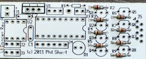
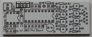
The design consists of a controller board with a PIC16F1826 and a ST485 RS485 receiver, a jumper for enabling the DMX Address Program Mode, eight resistors and 8 2N3904 transistors, and some connectors.
Connector Pinout
J1-Power
J1 is the 2 pin header located at the top left side of the PCB. The LEDancer can be powered by 5-24VDC. If you are using 5VDC, omit the voltage regulator and jumper the voltage regulator position by soldering a wire jumper to where the two outer pins of the regular would have gone in position U1 near the top left side of the PCB. If you are feeding greater than 5VDC, then you must use the on board voltage regulator.
Round Hole closest to the top of the board: Positive Power feed
Square Hole: Negative Power feed
J2 and J3-DMX Input and Output
The two 3 pin jumpers J2&J3 near the bottom left side of the board are used to bring DMX signals to and from the board. The 3 pin connectors are polarized and should be connected as follows:
Pin 1 is the Square hole of the three holes on the side towards the center of the board: Connect to DMX Ground
Pin 2 is the center hole of the three holes: Connect it to DMX Data -
Pin 3 is the left most hole of the three holes: Connect it to DMX Data +
Note that the two 3pin DMX connections are setup as a thru connection and can be used as either the input or output of the board. If the LEDancer is the last connection on a DMX data line, it may be necessary to add a 120 ohm terminating resistor to the unused DMX terminals between PIN 2 and Pin 3.
J4-ICSP Programming Header
J4 is the 6 pin header located in the bottom center of the board. J4 allows the PIC microprocessor to be programmed in place on the board by directly connecting a PICKIT2 or PICKIT3 programer.
Pin 1 is the square hole towards the right side of the board closest to D1.
J5 (2 pin)- DMX Address Programming Jumper
J5 is located in the top center of the PCB. By default the LEDancer is initially programmed to DMX address 1 by the firmware. The address may be changed in the device by either modifying the firmware or by using the special programming instructions listed below. You must temporarily install a shorting jumper across the two pins of J5 to use the special address setting packets.
J5(8 pin)- Output to LEDs
J5 is located along the right edge of the board and is a 8 pin connector used to connect to the LED Segment PCB. Pin1 of the connector is marked by the arrow next to it on the silkscreen.
Jumper Identification
J1-Power
J2-DMX
J3-DMX
J4-ICSP Programming Header
J5 (2 pin)- DMX Address Programming
J5(8 Pin)- Output to LEDs
Unumbered 3 Pin- ???
BOM - Bill Of Materials
To build LEDancer you will need parts from Mouser, LEDs, a LEDancer Controller PCB and LED Segment PCBs.
Mouser
| Mouser PN | Description | Qty | Optional |
| 538-22-03-2021 | Headers & Wire Housings VERT PCB HDR 2P TIN PLATING | 2 | |
| 538-22-03-2061 | Headers & Wire Housings VERT PCB HDR 6P TIN PLATING | 1 | |
| 538-22-03-2031 | Headers & Wire Housings VERT PCB HDR 3P TIN PLATING | 3 | |
| 80-C322C104K5R | Multilayer Ceramic Capacitors (MLCC) - Leaded 50volts 0.1uF 10% X7R | 1 | |
| 80-C322C334M5U5CA | Multilayer Ceramic Capacitors (MLCC) - Leaded 50volts 0.33uF 20% Z5U | 1 | **** |
| 299-82-RC | Carbon Film Resistors - Through Hole 82ohms 5% | 8 | |
| 512-2N3904TA | Transistors Bipolar (BJT) NPN Transistor General Purpose | 8 | |
| 511-ST485BN | Buffers & Line Drivers Hi-Spd Lo Pwr Trans | 1 | |
| 579-PIC16F1826-I/P | Microcontrollers (MCU) 3.5KB Flash 256 byte 32 MHz Int. Osc | 1 | |
| 571-1-390261-2 | IC & Component Sockets 8P ECONOMY TIN | 1 | |
| 571-1-390261-5 | IC & Component Sockets 18P ECONOMY TIN | 1 | |
| 604-WP7104GT | Standard LED - Through Hole GREEN TRANSPARENT | 1 | **** |
| 299-330-RC | Carbon Film Resistors - Through Hole 330ohms 5% | 1 | **** |
| TBD | 5V Voltage Regulator | 1 | **** |
| 151-8000-E | Headers & Wire Housings MINI JUMPER GF 6.0MM OPEN TYPE BLACK | 1 | **** |
| 291-120-RC | Carbon Film Resistors - Through Hole 120ohms 0.05 | 1 | **** |
LEDs
In addition, you will need up to 56 White Piranha Style Super flux LEDs. Other colors could be used, but you may need to adjust the resistor values on the controller board.
LEDancer Controller PCB
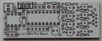
Each LEDancer Controller is capable of controlling up to 56 LEDs connected to it's output.
The PCB can be found at DIYLEDExpress.com
LED Segment PCBs

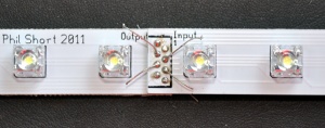
The original LED Segment board is an approximately 6" long modular board that contains 7 Piranha Style Superflux LEDs connected in a Charlieplexed fashion. The boards are designed to allow multiple boards to be daisy chained to allow various length tubes to be constructed. From 1 - 8 boards can be connected to each LEDancer controller creating a 6" to 48" long display tube.

The current LED Segment board is an approximately 12" long modular board that contains 14 Piranha Style Superflux LEDs connected in a Charlieplexed fashion. The boards are designed to allow multiple boards to be daisy chained to allow various length tubes to be constructed. From 1 - 4 boards can be connected to each LEDancer controller creating a 12" to 48" long display tube.
The LED Segment PCBs can be found at DIYLEDExpress.com
LED Connections
THIS SECTION IS OUT OF DATE.
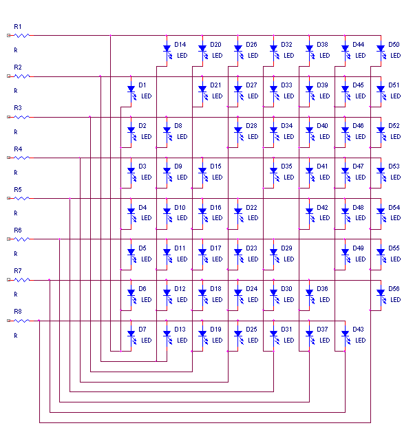
The LEDs can either be hand-wired on some sort of substrate (perhaps some plexiglass or linoleum), or a PCB can be designed to hold the LEDs. In all of the following diagrams LED1 is the LED controlled by the lowest DMX address, LED2 is next, and so forth. LED56 is the LED controlled by the highest (56'th) DMX address.
Schematic
Wirelist
Output1,LED1-C,LED2-C,LED3-C LED4-C,LED5-C,LED6-C,LED7-C,LED14-A,LED20-A,LED26-A,LED32-A,LED38-A,LED44-A,LED50-A
Output2,LED1-A,LED8-C,LED9-C,LED10-C,LED11-C,LED12-C,LED13-C,LED14-C,LED21-A,LED27-A,LED33-A,LED39-A,LED45-A,LED51-A
Output3,LED2-A,LED8-A,LED15-C,LED16-C,LED17-C,LED18-C,LED19-C,LED20-C,LED28-C,LED8-A,LED34-A,LED40-A,LED46-A,LED52-A
Output4,LED3-A,LED9-A,LED15-A,LED22-C,LED23-C,LED24-C,LED25-C,LED26-C,LED27-C,LED28-C,LED35-A,LED41-A,LED47-A,LED53-A
Output5,LED4-A,LED10-A,LED16-A,LED22-A,LED29-C,LED30-C,LED31-C,LED32-C,LED33-C,LED34-C,LED35-C,LED42-A,LED48-A,LED54-A
Output6,LED5-A,LED11-A,LED17-A,LED23-A,LED29-A,LED36-C,LED37-C,LED38-C,LED39-C,LED40-C,LED41-C,LED42-C,LED49-A,LED55-A
Output7,LED6-A,LED12-A,LED18-A,LED24-A,LED30-A,LED36-A,LED43-C,LED44-C,LED45-C,LED46-C,LED47-C,LED48-C,LED49-C,LED56-A
Output8,LED7-A,LED13-A,LED19-A,LED25-A,LED31-A,LED37-A,LED43-A,LED50-C,LED51-C,LED52-C,LED53-C,LED54-C,LED55-C,LED56-C
Stackable LED Board Design
Here is the schematic for a practical stackable board design. By connecting eight of these boards together (output to input, pin-1 to pin-1, etc) the previous schematic/wirelist can be readily built.
Assembly Instructions
Assembly of the LEDancer is done in three steps:
- Assembly of the LEDancer Controller.
- Assembly of the LED Segments.
- Connecting the two units together and installing them in a housing.
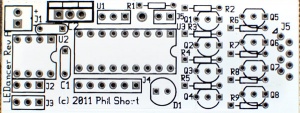
Begin by inspecting the PCBs to look for any defects such as cracks or breaks. The holes on the board should be open on both sides. Then inspect and sort out the various parts for the boards.
LEDancer Controller Assembly
- Install resistors
- Solder one 330 ohm resistor in R1 on top center of the PCB. The resistor is not polarized and can go either way. The 330 ohm resistor is optional and is only needed if you are installing the green LED on the controller board.
- Solder eight 82 ohm resistors in R2-R9 on the right side of the PCB. The resistors are not polarized and can go either way.
- Install IC sockets
- Solder one 8 pin IC socket on the left side of the PCB at U2. Install the socket with the notch facing to the right side of the PCB, matching the silkscreen.
- Solder one 18 pin IC socket on the left side of the PCB at U3. Install the socket with the notch facing to the right side of the PCB, matching the silkscreen.
- Install capacitors
- Solder one 0.1uf capacitor (marked 104)in C1 on the center left side of the PCB. The capacitor is not polarized and can go either way.
- Solder one 0.33uf capacitor (marked 334)in C2 on the top left side of the PCB. The capacitor is not polarized and can go either way.The 0.33uf capacitor is optional and is only needed if the voltage regulator is installed.
- Solder the eight 2N3904 transistors in Q1-Q8 on the right hand side of the PCB. The transistors are mounted with the flat side facing the top of the board matching the layout on the silkscreen.
- Solder the green LED in D1 in the bottom center of the PCB. The LED is polarized and the long lead goes to the right side of the PCB.The green LED is optional and is currently not used by the firmware.
- Install the headers. The short end of the header is soldered into the PCB.
- Solder two 2 pin headers in J1 on the top left of the PCB and J5 in the top center of the PCB. Header J1 is optional, you may choose to solder your power wires directly to the board.
- Solder three 3pin headers in J2 and J3 on the bottom left of the PCB and in the unmarked 3 position location in the top center of the PCB underneath where the silkscreen says U1 and R1. Headers J2 and J3 is optional, you may choose to solder your DMX Signal wires directly to the board.
- Solder one 6 pin header J4 in the bottom center of the PCB.
- Solder the voltage regulator in U1 on the top left side of the PCB. The voltage regulator is polarized and the heatsink side faces the top of the board.The voltage regulator is optional and is only needed if the power to the LEDancer is greater then 5V. If the LEDancer is powered by a regulated 5VDC power supply, you must omit the voltage regulator and install a wire jumper between the two outer pins of where the voltage regulator would go.
- Install ICs
LED Segment Board Assembly
It is strongly recommended that you test each LED before you solder it to the PCB using a LED tester. LED testers can be purchased on Ebay for less than $5.
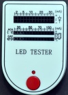
Based on how long you are making the LEDancer, you will need to assemble 1-4 LED Segment boards.
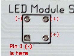
1. Solder the fourteen Superflux LEDs to the LED Segment PCB. The LEDs are polarized, there is one corner that is cut off and not square. The LED must be installed so that the orientation of the notched corner matches the silkscreen. If you are using the LEDs sold in the Fall2011 group buy, they are inserted with the notched corner matching the silkscreen. WARNING, Some LEDs from other vendors may have different orientations and they may need to be rotated 180 degrees from the silkscreen drawing. Please check to make sure know the correct orientation for your LEDs before soldering them to the PCB. The correct orientation of the LEDs would be to have the two cathode(-) pins of the LED in inserted in the two left side holes in the PCB.
2. Repeat Step #1 for each of your LED Segment PCBs.
3. The LED Segment PCBs need to be interconnected to make them the desired length. This is done by aligning the Input holes of one PCB with the Output holes of the next board. To do this lay one board on top of the next and carefully align the Input and Output Holes. You need to solder eight jumpers through these holes to each of the PCBs. Short lengths or wire or cutoff leads from resistors or other components work great.
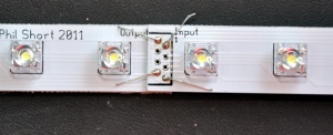
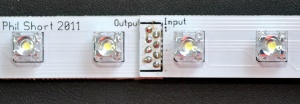
4. Repeat Step #3 until you have the correct number of LED Segment PCBs connected.
Final Assembly
- The LEDancer controller PCB must be connected to the LED Segment boards. There are two ways to accomplish that:
- The LEDancer Controller PCB may be soldered directly on to the top LED Segment board using the same technique as the LED Segment boards were joined. When built this way, with four LED Segement boards and the LEDancer module attached will be slightly longer than 4ft. If you use the group buy caps, you can fit the unit inside the caps on the tube.
- The LEDancer Controler PCB may be connected via jumper wires between the two boards.
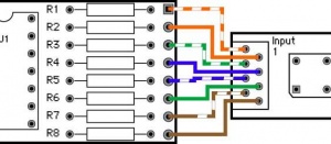
- Solder the wires from the LEDancer Controller to the Input of the top LED Segment PCB. The #1 wire on the controller side is near the top of the board and has an arrow pointing to it. It is soldered to the top left hole of the Input of the top LED Segment PCB, which is marked by the number 1 near the top of the board. The holes on both the LEDancer and the LED Segment board are offset into two columns, which are odd and even. So the #2 wire from the LEDancer Controller goes into the first hole in right column slightly below and to the right of where you soldered in the first wire. The #3 wire goes in the hole directly below the #1 wire in the left column. The #4 wire goes below the #2 wire. Continue until you have soldered in all eight wires. It is important that the correct holes on the controller and the segment boards are connected properly.
- Inspect all of the PCBs to make sure that there are no issues with the soldering.
- Connect the PICKIT programmer to the ICSP programming header J4. Note that Pin 1 is the right most pin and that must be connected to Pin1 of the PICKIT. Program the PIC using the firmware listed below.
- Apply power to the power input of the LEDancer Controller and send a DMX signal to the LEDancer and the LEDs should begin to light.
- The LEDancer Controller should be placed behind the top LED Segment PCB with some cardboard between the board to prevent them from shorting out. This assembly can then slide into the plastic housing.
- Apply the end caps and seal the tube to prevent rain from entering.
Congratulations, you have finished constructing your LEDancer.
Firmware
Here is the first version of the firmware. It uses an LED arrangement that is slightly different from the one documented above, so it won't be particularly useful. It is, however, the latest version that has been tested on hardware, so it is included here for reference.
Here is a second version of the firmware, modified to use the actual LED arrangement described earlier in this document. This is untested, however, because the author hasn't built the LED hardware yet that corresponds to the description above.
Here is a third version. The only changes from the second version are comments, particularly the hardware mapping list near the start of the file.
Here is the fourth version. It has changes to accommodate the current LED board revision, which is a common anode design rather than the original common-cathode design. It also has related changes to remove some ghosting issues.
Programming the DMX Address
The start address for the LEDancer can be set two ways:
- When the code is built, changing the line int eh code that reads #define DMX_START_ADDRESS 1 to what ever start address you want
- Use the program jumper and send a specially formatted DMX data stream.
Sending DMX data stream to program start address
To program the DMX address, first format (using Vixen) a DMX packet with the MSB of the address in the first byte of the packet and the LSB in the second byte. Then, install the jumper J5 (in the PCB layout above), and set up Vixen to send out the DMX packet with the new address. When the controller has accepted the new address and stored in the EEPROM, the first seven LEDs will come on and stay on solid. In order to resume normal operation you need to remove the jumper J5 and cycle power on the controller off and on.
The basic process using vixen is as follows:
- Choose your start address 1-505
- Create a vixen sequence with 2 channels and make it just 1 time period long
- Then you need to enter the start address into the two channels by using the intensity value feature of vixen set the values from 0-255 (Not 0-100%)
- If the start channel is >= 256, then enter “1” into the first channel, If less then 256 then enter “0” into the first channel
- If the start channel is >=256 then enter (start channel – 256) into the second channel
- If the start channel is < 256 then enter start channel into the second channel
- Example:
- If start address = 1
- Channel 1 = 0
- Channel 2 = 1
- If start address = 45
- Channel 1 = “0”
- Channel 2 = “45”
- If start address = 257
- Channel 1 = 1
- Channel 2 = 1
- If start address = 1
- Then, install the jumper J5 on the LEDancer and set up Vixen to send out the DMX packet with the new address.
- Run the sequence. When the controller has accepted the new address and stored in the EEPROM, the first seven LEDs will come on and stay on solid. In order to resume normal operation you need to remove the jumper J5 and cycle power on the controller off and on.
Video
Click here for a demo video of the LEDancer
