REN-C PCB ASSEMBLY INSTRUCTIONS: Difference between revisions
No edit summary |
|||
| (7 intermediate revisions by 3 users not shown) | |||
| Line 117: | Line 117: | ||
<center><blockquote>'''CONGATULATIONS!''' You have just finished building your Ren-C board.</blockquote></center> | <center><blockquote>'''CONGATULATIONS!''' You have just finished building your Ren-C board.</blockquote></center> | ||
==ZC and RENT requirements== | |||
When the REN64XB and RENC were first released, there was an extra board that was made available, the RENT. The function of the RENT was to provide power and a source of ZC to the controllers. | |||
The RENC did not require separate power as it draws 5 V DC from the GRINCH board. What it does need is a source of ZC. | |||
What is ZC? Zero Cross reference. When dimming, the RENC needs to know the start of the AC signal waveform, i.e. when it crosses over Zero V AC. A small sample of AC voltage is required to obtain the ZC. | |||
There are a couple of options. | |||
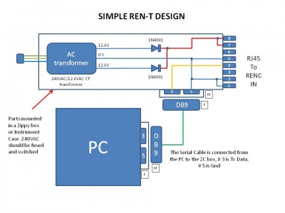
Option 1 - Use a small AC stepdown transformer (12.6V CT) and build a simple circuit to rectify the Low V AC to DC. | |||
[[Image:Simple RenT Design.jpg | 400px]] | |||
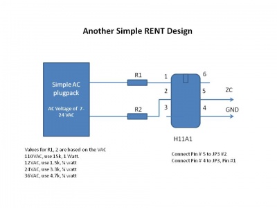
Option 2 - Use a small AC stepdown transformer (12.6V CT) and build a OPTOISOLATOR circuit to provide a source of ZC. | |||
[[Image:Another RENT (H11A1).jpg | 400px]] | |||
Option 3 - Use a centertap transformer with 2 diodes | |||
http://doityourselfchristmas.com/forums/showpost.php?p=91084&postcount=23 | |||
=='''Parts Listing (BOM)'''== | =='''Parts Listing (BOM)'''== | ||
| Line 243: | Line 263: | ||
:[http://en.wikipedia.org/wiki/Electronic_symbol Electronic Symbols] | :[http://en.wikipedia.org/wiki/Electronic_symbol Electronic Symbols] | ||
[[Category:Ren-C]] | |||
[[Category:DIYC Index]] | |||
Latest revision as of 03:08, 29 January 2011
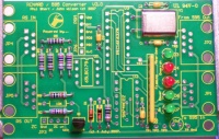
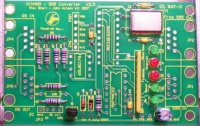
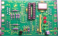
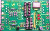
Board Assembly
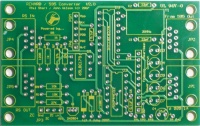
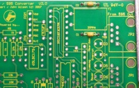
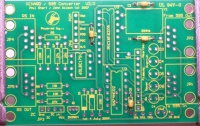
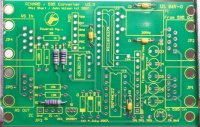
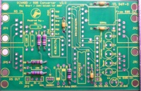
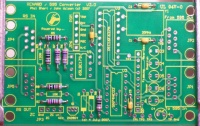
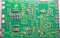
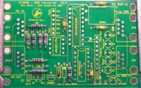
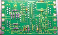
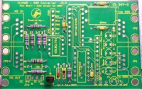
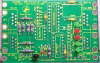
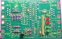
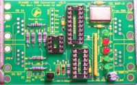
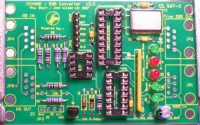
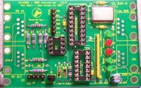
- Assembling the Ren-C should be fairly easy for most hobbyists.
- The following sequence of steps is by no means the only way to do this. It is simply a suggested order of events to achieve the desired goal.
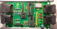
CONGATULATIONS! You have just finished building your Ren-C board.
ZC and RENT requirements
When the REN64XB and RENC were first released, there was an extra board that was made available, the RENT. The function of the RENT was to provide power and a source of ZC to the controllers.
The RENC did not require separate power as it draws 5 V DC from the GRINCH board. What it does need is a source of ZC.
What is ZC? Zero Cross reference. When dimming, the RENC needs to know the start of the AC signal waveform, i.e. when it crosses over Zero V AC. A small sample of AC voltage is required to obtain the ZC.
There are a couple of options.
Option 1 - Use a small AC stepdown transformer (12.6V CT) and build a simple circuit to rectify the Low V AC to DC.
Option 2 - Use a small AC stepdown transformer (12.6V CT) and build a OPTOISOLATOR circuit to provide a source of ZC.
Option 3 - Use a centertap transformer with 2 diodes http://doityourselfchristmas.com/forums/showpost.php?p=91084&postcount=23
Parts Listing (BOM)
| PART NUMBER (Mouser PN# unless noted) |
QTY | REF | NOMENCLATURE |
|---|---|---|---|
| 815-AB-20-B2 | 1 | Y1 | 20.000 MHz Crystal, HC49U case |
| 581-SA102A220JAR | 2 | C1,C2 | 22 pf, 200V NPO Axial Ceramic Capacitors |
| 581-SA105E104MAR | 2 | C3,C5 | .1 uF, 50V, Z5U Axial Ceramic Capacitors |
| 140-XRL10V10-RC | 1 | C4 | 10 uF, 10V, Radial Aluminum Electrolytic Cap |
| 604-WP7104GT | 5 | D3-D7 | Green Transparent LED, 3mm |
| 604-WP7104IT | . | D3-D7 | Red LED, 3mm (alternative to Green LED) |
| 595-SN65LBC179P | 1 | U1 | RS485 Receiver/Transmitter (DIP8) |
| 511-M74HC02 | 1 | U2 | Quad 2-Input NOR Gate (DIP14) |
| 579-PIC16F627A-I/P | 1 | U3 | PICmicro - PIC16Fxxx Flash MCUs 1.75KB 224 RAM 16I/O |
| 271-1K-RC | 2 | R4,R5 | Metal Film Resistor, 1K, 1/4W |
| 271-10K-RC | 2 | R8,R9 | Metal Film Resistor, 10K, 1/4W |
| 271-27K-RC | 3 | R2,R6,R7 | Metal Film Resistor, 27K, 1/4W |
| 271-120-RC | 1 | R3 | Metal Film Resistor, 120, 1/4W |
| 652-4610X-2LF-470 | 1 | RP | Resistor Network, 470, 10-Pin SIP, Isolated Resistors |
| 78-1N5229B | 1 | D1 | Diode, Zener, 4.3V, 0.5W |
| 78-1N5239B | 1 | D2 | Diode, Zener, 9.1V, 0.5W |
| 571-5520251-4 | 4 | JP1,JP2,JP4,JP5 | Modular Jack, Right-Angle, 8-8 |
| 571-1032394 | 1 | JP3 | Vertical Header, 4 Pin |
| 571-1032396 | 1 | JP6 | Vertical Header, 6 Pin |
| 571-41032390 | . | . | Vertical Header, 40 Pin (can be broken into smaller headers for above) |
| 512-2N3904TA | 1 | Q1 | Transistor, NPN, small signal |
| 571-1-390261-5 | 1 | . | 18 Pin DIP socket (optional) |
| 571-1-390261-3 | 1 | . | 14 Pin DIP socket (optional) |
| 571-1-390261-2 | 1 | . | 08 Pin DIP Socket (optional) |
Below is the same parts list as above but it is formatted for direct importing into the Mouser BOM feature. Just copy and paste the list as is. The last 3 parts listed correspond to the optional items listed above.
815-AB-20-B2	1
581-SA102A220JAR	2
581-SA105E104MAR	2
140-XRL10V10-RC	1
604-WP7104GT	5
595-SN65LBC179P	1
511-M74HC02	1
579-PIC16F627A-I/P	1
271-1K-RC	2
271-10K-RC	2
271-27K-RC	3
271-120-RC	1
652-4610X-2LF-470	1
78-1N5229B	1
78-1N5239B	1
571-5520251-4	4
512-2N3904TA	1
571-1032394	1
571-1032396	1
571-1-390261-5	1
571-1-390261-3	1
571-1-390261-2	1
