24 Channel Renard with SSR Assembly Instructions: Difference between revisions
| (40 intermediate revisions by 7 users not shown) | |||
| Line 1: | Line 1: | ||
===NOTE=== | |||
'''This is not the Renard SS24, the popular 24 Channel Controller that is sold in the group buys. For information about that board go to [[Renard SS24 Controller Board]].'''<br/> | |||
=== Renard 24 Information === | |||
The Renard 24 Dimmer is Frank Kostyun's 24 Channel All-In-One Christmas Lights Controller. | |||
[http://www.kostyun.com Frank Kostyun's Renard 24 Info Page] | |||
[http://store.kostyun.com/prestashop Frank Kostyun's Online Store for Renard 24 Co-Ops] | |||
<br> | |||
Co-Ops are run throughout the year for the purchase of boards. There are also additional co-ops run for parts, and heatsinks. | |||
[http://http://www.doityourselfchristmas.com/forums/forumdisplay.php?f=18 DoItYourselfChristmas.com's Group Buys Forum] | |||
WLC Ventures now stocks the Renard 24HC [http://wlcventures.com/zencart/index.php?main_page=advanced_search_result&search_in_description=1&keyword=Renard+24HC here]. | |||
=== Schematic=== | === Schematic=== | ||
| Line 7: | Line 20: | ||
[[Media:Renard64_sch_001.pdf]] | [[Media:Renard64_sch_001.pdf]] | ||
(please note, the schematic is identical to the Renard64) | (please note, the schematic is identical to the Renard64) | ||
RavingLunatic created this schematic by tracing out the board. Note that this is NOT an official schematic, may have errors, and some reference designators are were derived for this schematic. | |||
[[Media:Renard24 V33 Schematic package.pdf]] | |||
=== Layout === | === Layout === | ||
| Line 12: | Line 29: | ||
[[Image:REN_24_25.jpg]] | [[Image:REN_24_25.jpg]] | ||
=== COOP PCB | === COOP PCB V3.0 === | ||
[[Image: | [[Image:26-72.jpg]] | ||
=== Co-Op Board 3. | === Co-Op Board 3.3 Assembly Instructions === | ||
For a full step by step document on how to build the Renard 24, please click the following link: | |||
[http://www.doityourselfchristmas.com/wiki/images/6/63/Building_ren_24.pdf Renard 24 Assembly Instructions] - [http://www.kostyun.com/PDF/building_ren_24.pdf original] | |||
=== Testing the v 3.3 Board=== | |||
Version 3.3 has 7 test points (TP1 to TP7) | |||
TP1: GND<br> | |||
TP2: +5VDC<br> | |||
TP3: +12v<br> | |||
TP4: 12vac<br> | |||
TP5: 12vac<br> | |||
TP6: RS485A / RJ45 Pin 5<br> | |||
TP7: RS485B / RJ45 Pin 4<br> | |||
=== Design Notes for v 3.3 Board=== | |||
The COMM FR LED pads are backwards - the cathode (short leg on the LED) will go into the round hole | |||
=== Renard 24 Jumper Settings and Options === | |||
''Version 2.5 and Greater<br>'' | |||
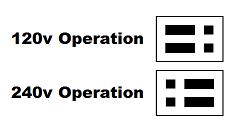
120/240v Jumpers: Allow for setting the transformers input voltage (labeled as JP1 and JP2.)<br> | |||
[[Image:120v240v.jpg]]<br> | |||
Zero Cross: If on, the board will insert the zero cross signal on the RJ45 pin 3 (labeled as JP3.) This is used to send a ZC signal to another board such as a Ren64 or Ren16.<br> | |||
[[Image:Zc1.jpg]]<br> | |||
<br> | |||
Transformer On/Off: If on, the transformer recieves power from the left power input.<br> | |||
[[Image:Transformer.jpg]]<br> | |||
<br> | |||
''Version 3.3 and Greater<br>'' | |||
12v Jumpers: Located below the transformer, these can be installed to use the board in 12vac only mode (for use with MR16 LED lamps, also labeled as JP5 and JP6.)<br> | |||
=== Firmware === | |||
All Renard Firmware is located here: [[Renard_Firmware]] | |||
There is also pre-compiled firmware here: [http://www.kostyun.com/?page_id=139/ Renard 24/Renard 24LV firmware Page] | |||
=== BOM === | === BOM === | ||
| Line 28: | Line 79: | ||
<pre> | <pre> | ||
PCB | PCB | ||
1 | 1 Ren24 v3.3 Renard 24-Port PCB | ||
Board Specific Parts: | |||
571-7969494 1 '''See note below for v3.3''' | |||
571-7969494 1 | 595-SN75176BP 2 '''RS-485 Interface ICs Bus Diff''' | ||
595-SN75176BP 2 | 511-L7805CV 1 '''LM7805 Voltage Regulator''' | ||
511-L7805CV 1 | 821-DB102G 1 '''subsitute part 512-DF01M''' | ||
821-DB102G 1 | 532-7136DG 1 '''Heat Sink for 5V regulator''' | ||
532-7136DG 1 | 271-27K-RC 3 '''27k ohm 1/4 watt resistor''' | ||
271-27K-RC 3 | 271-1K-RC 4 '''1k ohm 1/4 watt resistor''' | ||
271-1K-RC 4 | 271-120-RC 1 '''120ohm 1/4 watt resistor''' | ||
271-120-RC 1 | 625-1N4001-E3 1 '''Standard Rectifiers Vr/50V Io/1A''' | ||
625-1N4001-E3 1 | 78-1N5239B 2 '''Zener Diodes 9.1 Volt 0.5 Watt''' | ||
78-1N5239B 2 | 838-3FD-320 1 '''Larger Transformer use part 838-3FD-420''' | ||
838-3FD-320 1 | 782-H11AA1 1 '''Optocouplers Bi-Directional Input''' | ||
782-H11AA1 1 | 520-TCF1843-X 1 '''Full Size Crystal Clock Oscillators DIP-14 5V 18.432MHz''' | ||
520-TCF1843-X 1 | 140-HTRL25V1000-RC 1 '''Hi-Temp Radial Electrolytic Capacitors 25V 1000uF 105C''' | ||
140-HTRL25V1000-RC 1 | 140-HTRL25V10-RC 1 '''Hi-Temp Radial Electrolytic Capacitors 25V 10uF 105C''' | ||
140-HTRL25V10-RC 1 | 534-3517 4 '''Fuse Clips and Holders PC FUSE CLIP 5 MM''' | ||
534-3517 4 | 504-GMA-15 2 '''5mm x 20mm Fast Acting Fuses 125VAC 15A Fast Acting''' | ||
504-GMA-15 2 | |||
Parts from the Common Parts List: (Common parts are the parts that are not unique to the Ren24, and may also be used in other designs) | Parts from the Common Parts List: (Common parts are the parts that are not unique to the Ren24, and may also be used in other designs) | ||
511-BTA08-400B 24 '''Triac Driver (24 needed) or 511-BTA04-700T more sensitive triac for LED's))''' | |||
859-MOC3023 24 '''MOC 3023 Optocoupler''' | |||
MOC 3023 Optocoupler | 579-PIC16F688-I/P 3 '''Microchip PIC 16F1688''' | ||
Microchip PIC 16F1688 | 604-WP63ID 4 '''Red T1 3/4 LED, or any 10-30ma LED''' | ||
Red T1 3/4 LED | 604-WP1503GD 1 '''Green T1 3/4 LED or any 10-30ma LED''' | ||
Green T1 3/4 LED | 271-180-RC 24 '''180ohm 1/4 watt resistor''' | ||
180ohm 1/4 watt resistor | 271-680-RC 29 '''680ohm 1/4 watt resistor''' | ||
680ohm 1/4 watt resistor | 581-SA105E104MAR 5 '''.10 uF Ceramic Capacitor''' | ||
.10 uF Ceramic Capacitor | 571-9-146281-0 1 '''.100 three pin header(4 needed) Part specified is a 40 pin, cut off size that is needed.''' | ||
.100 three pin header (4 needed) Part specified is a 40 pin, cut off size that is needed. | 571-2-382811-1 4 '''.100 Shunt (4 needed) You may also "steal" these off of old computer parts.''' | ||
.100 Shunt (4 needed) You may also "steal" these off of old computer parts. | 571-1-390261-2 2 '''8 pin DIP socket''' | ||
571-1-390261-3 3 '''14 pin DIP socket''' | |||
8 pin DIP socket | 571-1-390261-1 26 '''Optional 6 Pin Socket for Optocoupler & H11AA1''' | ||
14 pin DIP socket | 571-5556416-1 2 '''RJ45 Sockets (2 needed) orientation doesn't matter. Specified part is same as the Ren64''' | ||
RJ45 Sockets (2 needed) orientation doesn't matter. Specified part is same as the Ren64 | |||
PART OPTION #1 - Using Screw Down Terminals | PART OPTION #1 - Using Screw Down Terminals | ||
571-2828376 6 '''6 Position Screw Down Terminal (Ren24 2.5 needs 4 of these)''' | |||
534-1287 | 158-P02EK508A3-E 4 '''3 Position Angled Screw Down Terminal''' | ||
158-P02EHK508V3-E 1 '''3 Position Screw Down Terminal (power input) - higher current rating than prior part''' | |||
158-P02EHK508V2-E 1 '''2 Position Screw Down Terminal (power input) - higher current rating than prior part''' | |||
Spade Terminals | |||
534-1287 53 '''Spade Terminals (52 needed for board v3.0)''' | |||
Optional Parts for The Board: | |||
12VAC Operation | |||
571-9-146281-0 1 '''.100 two pin header(2 needed)''' | |||
571-2-382811-1 2 '''.100 Shunt (2 needed) You may also "steal" these off of old computer parts.''' | |||
838-3FD-316 0 '''Transformer is ELIMINATED from the board in this option''' | |||
</pre> | </pre> | ||
[http://www.kostyun.com/PDF/BOM/Ren24_Bom_Mouser.txt Renard 24 Importable BOM - Screw Terminals] All parts valid 05/10/2009 | |||
==== Parts Changes From Board 2.5 to 3.3 ==== | |||
With multiple changes to the board, and the changes of parts that has occurred over time, if you still are having an older board to solder up, but still need parts - you can use a current Co-Op purchase for parts if you choose - and you will just have a few extra parts left over (and also still be able to enjoy the significant savings the co-op gets you.) | |||
<br> | |||
You will end up with: | |||
2 to 3 jumper sets | |||
2 extra resistors | |||
2 extra LEDs | |||
2 of 71-2828376 - 6 pin connector | |||
and 4 of 158-P02EK508A3-E - 3 pin angled connector | |||
On parts 158-P02EHK508V2-E and 158-P02EHK508V3-E - the Five Pin Terminal, it is reccommended to just cut off the pin for one of the plugs. | |||
==== PC to Renard Cable ==== | |||
The Renard 24 board has on-board power supply circuitry and on-board zero-crossing circuitry, so all that it needs on the RJ45 cable are data signals and ground. If you are using RS232 input and connecting it directly to the PC serial port, the following cable pin outs will work: | |||
'''Version 3.0 Board:''' | |||
PC DB9 Pin 3 to RJ45-pin 4 | |||
PC DB9 Pin 5 to RJ45-pins 1,2,5 (pins 1 and 5 are required, pin 2 is optional). | |||
[[Image:Ren24V3.jpg]] | |||
If you are using a RS-232 to RS-485 converter, the pinout is Pin 5 to A+ | |||
and Pin 4 to B-. This is the same as for the Ren 16. | |||
'''Version 2.5 Board:''' | |||
PC DB9 Pin 3 to RJ45-pin 5 | |||
PC DB9 Pin 5 to RJ45-pins 1,2,4 (pins 1 and 4 are required, pin 2 is optional). | |||
[[Image:Ren24v25.jpg]] | |||
'''NOTE:''' ''The 2.5 cable will not work with the Renard16, Renard64 or Ren-C boards because pins 4 and 5 on the version 2.5 Renard24 are reversed from those other boards.'' | |||
[[Image:Db9f.gif]] | |||
'''Female DB9 connector as if you were looking into the end of it from the outside.''' | |||
The Renard24 3.0 or greater will pass the zero cross and power to other boards connected to it (such as a Renard64 or Renard16.) | |||
=== Board Version History === | |||
Revision 1 board (unreleased, development board only) | |||
Revision 2 board (unreleased, development board only) | |||
Revision 2.5 board (2007 Co-Op) | |||
Revision 3.0 board (2008 Co-Op #1 and #2) | |||
Revision 3.1 board (unreleased, development board only) | |||
Revision 3.3 board (2008 Co-Op #3 and 2009 Co-Ops #1 and #2) | |||
== Revision History == | == Revision History == | ||
| Line 110: | Line 207: | ||
01/14/2008 Increase the size of the board to add a neutral buss onto the board. | 01/14/2008 Increase the size of the board to add a neutral buss onto the board. | ||
01/14/2008 Added support for either spade terminals or screw down terminals. | 01/14/2008 Added support for either spade terminals or screw down terminals. | ||
02/20/2008 Added power pass through on pins 7/8 and ground on pins 1/2. | |||
07/31/2008 Added two additional diagnostic LEDs for the diagnostic firmware. | |||
07/31/2008 Change 4 pin input to 5 pin input to allow for easy jumpering of sides. | |||
07/31/2008 Added jumpers below transformer for 12vac use. | |||
03/18/2009 Corrected silkscreen and pads of the Comm FR test LED | |||
Errata for Rev 1 PCB - | Errata for Rev 1 PCB - | ||
| Line 125: | Line 227: | ||
2) Silkscreen needs to have some clarification done for part orientation. | 2) Silkscreen needs to have some clarification done for part orientation. | ||
Errata for Rev 3.0 PCB - (Co-Op Board) | |||
2) | 1) Some holes to small for spade tabs | ||
2) still some spacing issues around the voltage regulator heatsink. | |||
Errata for Rev 3.3 PCB - (Co-Op Board) | |||
1) COMM FR LED pads are backwards | |||
=== Design Notes for v 2.5 Co-Op Board=== | === Design Notes for v 2.5 Co-Op Board=== | ||
| Line 140: | Line 247: | ||
The + pin of the DB102 is on the bottom right both of the ~ should be on the left. | The + pin of the DB102 is on the bottom right both of the ~ should be on the left. | ||
The parts list | The original parts parts list had a 100uF cap, ignore it - as its not needed (Deleted from BOM) There is a extra 1uF on the board, also not needed. | ||
The 7805 (flat side) goes to the top of the board. | The 7805 (flat side) goes to the top of the board. | ||
| Line 146: | Line 253: | ||
The heatsink for the 7805 should be trimmmed at the bottom to allow for proper fit. | The heatsink for the 7805 should be trimmmed at the bottom to allow for proper fit. | ||
The fuse clips are two tight for the board - now sure how this happened - I need to look into this more - as this is the part that I ordered last year and it fits fine. | The fuse clips are two tight for the board - now sure how this happened - I need to look into this more - as this is the part that I ordered last year and it fits fine. Use pliers to squeeze the pins together a bit and they will fit in. | ||
The jumpers on the board are for 120/240v operation. If you don't plan on using the boards on 120v these can be hard soldered with a jumper wire. | The jumpers on the board are for 120/240v operation. If you don't plan on using the boards on 120v these can be hard soldered with a jumper wire. | ||
There are two resistors that are close to the output blocks, when installing them, leave them up a bit so they can be pushed back a little bit. | There are two resistors that are close to the output blocks, when installing them, leave them up a bit so they can be pushed back a little bit. | ||
[[Category:DIYC Controllers]] | |||
[[Category:Renard]] | |||
[[Category:Renard 24]] | |||
[[Category:DIYC Index]] | |||
[[ | |||
[[ | |||
[[ | |||
Latest revision as of 17:09, 26 July 2013
NOTE
This is not the Renard SS24, the popular 24 Channel Controller that is sold in the group buys. For information about that board go to Renard SS24 Controller Board.
Renard 24 Information
The Renard 24 Dimmer is Frank Kostyun's 24 Channel All-In-One Christmas Lights Controller.
Frank Kostyun's Renard 24 Info Page
Frank Kostyun's Online Store for Renard 24 Co-Ops
Co-Ops are run throughout the year for the purchase of boards. There are also additional co-ops run for parts, and heatsinks.
DoItYourselfChristmas.com's Group Buys Forum
WLC Ventures now stocks the Renard 24HC here.
Schematic
Media:Renard64_sch_001.pdf (please note, the schematic is identical to the Renard64)
RavingLunatic created this schematic by tracing out the board. Note that this is NOT an official schematic, may have errors, and some reference designators are were derived for this schematic.
Media:Renard24 V33 Schematic package.pdf
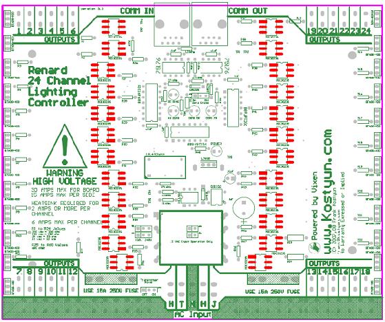
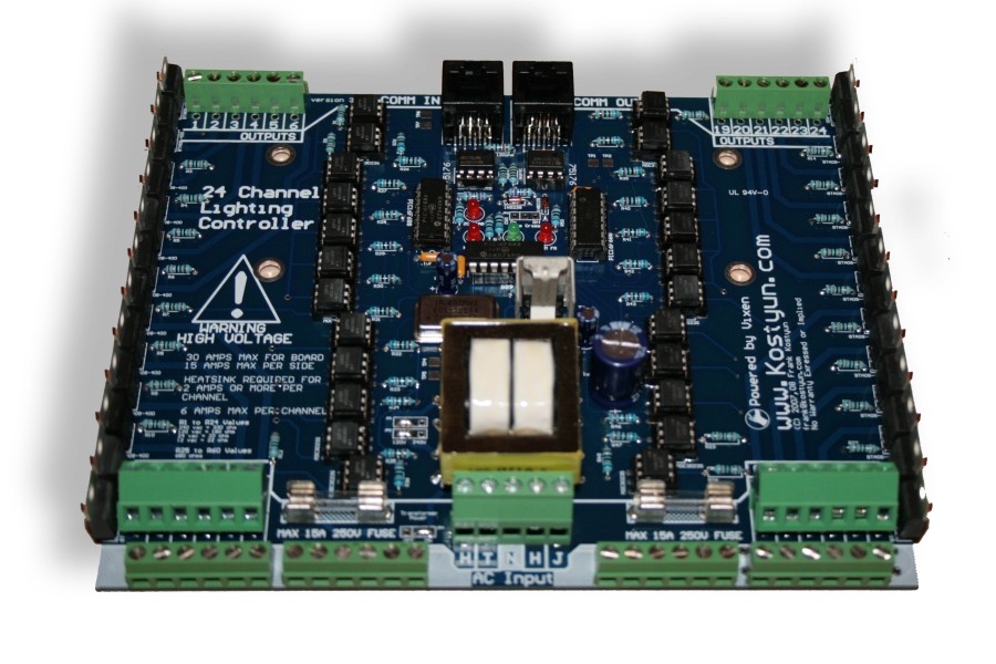
Layout
COOP PCB V3.0
Co-Op Board 3.3 Assembly Instructions
For a full step by step document on how to build the Renard 24, please click the following link:
Renard 24 Assembly Instructions - original
Testing the v 3.3 Board
Version 3.3 has 7 test points (TP1 to TP7)
TP1: GND
TP2: +5VDC
TP3: +12v
TP4: 12vac
TP5: 12vac
TP6: RS485A / RJ45 Pin 5
TP7: RS485B / RJ45 Pin 4
Design Notes for v 3.3 Board
The COMM FR LED pads are backwards - the cathode (short leg on the LED) will go into the round hole
Renard 24 Jumper Settings and Options
Version 2.5 and Greater
120/240v Jumpers: Allow for setting the transformers input voltage (labeled as JP1 and JP2.)
Zero Cross: If on, the board will insert the zero cross signal on the RJ45 pin 3 (labeled as JP3.) This is used to send a ZC signal to another board such as a Ren64 or Ren16.
![]()
Transformer On/Off: If on, the transformer recieves power from the left power input.
![]()
Version 3.3 and Greater
12v Jumpers: Located below the transformer, these can be installed to use the board in 12vac only mode (for use with MR16 LED lamps, also labeled as JP5 and JP6.)
Firmware
All Renard Firmware is located here: Renard_Firmware There is also pre-compiled firmware here: Renard 24/Renard 24LV firmware Page
BOM
PCB
1  Ren24 v3.3                             Renard 24-Port PCB

Board Specific Parts:

571-7969494 1             '''See note below for v3.3'''
595-SN75176BP 2           '''RS-485 Interface ICs Bus Diff'''
511-L7805CV 1             '''LM7805 Voltage Regulator'''
821-DB102G 1              '''subsitute part 512-DF01M'''
532-7136DG 1              '''Heat Sink for 5V regulator'''
271-27K-RC 3              '''27k ohm 1/4 watt resistor'''
271-1K-RC 4               '''1k ohm 1/4 watt resistor'''
271-120-RC 1              '''120ohm 1/4 watt resistor'''
625-1N4001-E3 1           '''Standard Rectifiers Vr/50V Io/1A'''
78-1N5239B 2              '''Zener Diodes 9.1 Volt 0.5 Watt'''
838-3FD-320 1             '''Larger Transformer use part 838-3FD-420'''
782-H11AA1 1              '''Optocouplers Bi-Directional Input'''
520-TCF1843-X 1           '''Full Size Crystal Clock Oscillators DIP-14 5V 18.432MHz'''
140-HTRL25V1000-RC 1      '''Hi-Temp Radial Electrolytic Capacitors 25V 1000uF 105C'''
140-HTRL25V10-RC 1        '''Hi-Temp Radial Electrolytic Capacitors 25V 10uF 105C'''
534-3517 4                '''Fuse Clips and Holders PC FUSE CLIP 5 MM'''
504-GMA-15 2              '''5mm x 20mm Fast Acting Fuses 125VAC 15A Fast Acting'''


Parts from the Common Parts List: (Common parts are the parts that are not unique to the Ren24, and may also be used in other designs)

511-BTA08-400B 24         '''Triac Driver (24 needed) or 511-BTA04-700T more sensitive triac for LED's))'''
859-MOC3023 24            '''MOC 3023 Optocoupler'''
579-PIC16F688-I/P 3       '''Microchip PIC 16F1688'''
604-WP63ID 4              '''Red T1 3/4 LED, or any 10-30ma LED'''
604-WP1503GD 1            '''Green T1 3/4 LED or any 10-30ma LED'''
271-180-RC 24             '''180ohm 1/4 watt resistor'''
271-680-RC 29             '''680ohm 1/4 watt resistor'''
581-SA105E104MAR 5        '''.10 uF Ceramic Capacitor'''
571-9-146281-0 1          '''.100 three pin header(4 needed) Part specified is a 40 pin, cut off size that is needed.'''
571-2-382811-1 4          '''.100 Shunt (4 needed) You may also "steal" these off of old computer parts.'''
571-1-390261-2 2          '''8 pin DIP socket'''
571-1-390261-3 3          '''14 pin DIP socket'''
571-1-390261-1 26         '''Optional 6 Pin Socket for Optocoupler & H11AA1'''
571-5556416-1 2           '''RJ45 Sockets (2 needed) orientation doesn't matter. Specified part is same as the Ren64'''

PART OPTION #1 - Using Screw Down Terminals

571-2828376 6             '''6 Position Screw Down Terminal (Ren24 2.5 needs 4 of these)'''
158-P02EK508A3-E 4        '''3 Position Angled Screw Down Terminal'''
158-P02EHK508V3-E 1       '''3 Position Screw Down Terminal (power input) - higher current rating than prior part'''
158-P02EHK508V2-E 1       '''2 Position Screw Down Terminal (power input) - higher current rating than prior part'''

Spade Terminals

534-1287 53               '''Spade Terminals (52 needed for board v3.0)'''

Optional Parts for The Board:

12VAC Operation
571-9-146281-0 1          '''.100 two pin header(2 needed)'''
571-2-382811-1 2          '''.100 Shunt (2 needed) You may also "steal" these off of old computer parts.'''
838-3FD-316 0             '''Transformer is ELIMINATED from the board in this option'''
Renard 24 Importable BOM - Screw Terminals All parts valid 05/10/2009
Parts Changes From Board 2.5 to 3.3
With multiple changes to the board, and the changes of parts that has occurred over time, if you still are having an older board to solder up, but still need parts - you can use a current Co-Op purchase for parts if you choose - and you will just have a few extra parts left over (and also still be able to enjoy the significant savings the co-op gets you.)
You will end up with:
2 to 3 jumper sets
2 extra resistors
2 extra LEDs
2 of 71-2828376 - 6 pin connector
and 4 of 158-P02EK508A3-E - 3 pin angled connector
On parts 158-P02EHK508V2-E and 158-P02EHK508V3-E - the Five Pin Terminal, it is reccommended to just cut off the pin for one of the plugs.
PC to Renard Cable
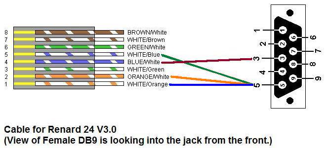
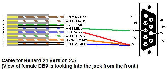
The Renard 24 board has on-board power supply circuitry and on-board zero-crossing circuitry, so all that it needs on the RJ45 cable are data signals and ground. If you are using RS232 input and connecting it directly to the PC serial port, the following cable pin outs will work:
Version 3.0 Board:
PC DB9 Pin 3 to RJ45-pin 4
PC DB9 Pin 5 to RJ45-pins 1,2,5 (pins 1 and 5 are required, pin 2 is optional).
If you are using a RS-232 to RS-485 converter, the pinout is Pin 5 to A+ and Pin 4 to B-. This is the same as for the Ren 16.
Version 2.5 Board:
PC DB9 Pin 3 to RJ45-pin 5
PC DB9 Pin 5 to RJ45-pins 1,2,4 (pins 1 and 4 are required, pin 2 is optional).
NOTE: The 2.5 cable will not work with the Renard16, Renard64 or Ren-C boards because pins 4 and 5 on the version 2.5 Renard24 are reversed from those other boards.
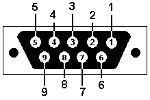 Female DB9 connector as if you were looking into the end of it from the outside.
The Renard24 3.0 or greater will pass the zero cross and power to other boards connected to it (such as a Renard64 or Renard16.)
Board Version History
Revision 1 board (unreleased, development board only)
Revision 2 board (unreleased, development board only)
Revision 2.5 board (2007 Co-Op)
Revision 3.0 board (2008 Co-Op #1 and #2)
Revision 3.1 board (unreleased, development board only)
Revision 3.3 board (2008 Co-Op #3 and 2009 Co-Ops #1 and #2)
Revision History
 01/20/2007 Initial Design
 03/20/2007 Revision 2 submitted to test manufacturing.
 07/15/2007 Changed RJ45 to comply with current Renard standards.
 07/15/2007 Added additional holes for a larger transformer.
 07/15/2007 Added transformer voltage selection jumpers, will allow for 120/240v operation for our friends down under.
 07/15/2007 Changed fuse size to 5x20mm fuse from AG3 fuse.
 07/16/2007 Added option for DIP or SMT MOC2032 optos.
 08/20/2007 Version 2.5 submitted to test manufacturing.
 10/01/2007 Making small adjustments based on user feedback to ease setup of board. No major changes made.
 01/14/2008 Corrected RS485 pins 4/5 to match Ren16 and Ren64
 01/14/2008 Minor silkscreen corrections.
 01/14/2008 Increase the size of the board to add a neutral buss onto the board.
 01/14/2008 Added support for either spade terminals or screw down terminals.
 02/20/2008 Added power pass through on pins 7/8 and ground on pins 1/2.
 07/31/2008 Added two additional diagnostic LEDs for the diagnostic firmware.
 07/31/2008 Change 4 pin input to 5 pin input to allow for easy jumpering of sides.
 07/31/2008 Added jumpers below transformer for 12vac use.
 03/18/2009 Corrected silkscreen and pads of the Comm FR test LED
Errata for Rev 1 PCB -
 1) Onboard regulator not functioning properly: needed addition of 1000uF capacator. (corrected in rev 2.0 board)
 2) Outputs are out of order. (corrected in rev 2.0 board)
 3) Triacs are located to close together. (corrected in rev 2.0 board)
Errata for Rev 2 PCB -
1) Outputs 17/18 are swapped. (corrected in rev 2.5 board)
Errata for Rev 2.5 PCB - (Co-Op Board)
 1) RS485 traces swapped from the Ren16/Ren64 pin config. (To be corrected in Rev 3.0 Board)
 2) Silkscreen needs to have some clarification done for part orientation.
Errata for Rev 3.0 PCB - (Co-Op Board)
 1) Some holes to small for spade tabs
 2) still some spacing issues around the voltage regulator heatsink.
Errata for Rev 3.3 PCB - (Co-Op Board)
1) COMM FR LED pads are backwards
Design Notes for v 2.5 Co-Op Board
Pin 1 of the crystal is on the bottom left.
Pin 1 of the transformer is on the top left.
The cathode (striped) pin of the 1N4001 diode is on the top.
The correct designation of the capacitor on the top right is .1uF, not .1F.
The + pin of the DB102 is on the bottom right both of the ~ should be on the left.
The original parts parts list had a 100uF cap, ignore it - as its not needed (Deleted from BOM) There is a extra 1uF on the board, also not needed.
The 7805 (flat side) goes to the top of the board.
The heatsink for the 7805 should be trimmmed at the bottom to allow for proper fit.
The fuse clips are two tight for the board - now sure how this happened - I need to look into this more - as this is the part that I ordered last year and it fits fine. Use pliers to squeeze the pins together a bit and they will fit in.
The jumpers on the board are for 120/240v operation. If you don't plan on using the boards on 120v these can be hard soldered with a jumper wire.
There are two resistors that are close to the output blocks, when installing them, leave them up a bit so they can be pushed back a little bit.
