Serial, RS232: Difference between revisions
Wvengineer (talk | contribs) mNo edit summary |
No edit summary |
||
| (7 intermediate revisions by 2 users not shown) | |||
| Line 41: | Line 41: | ||
</TABLE> | </TABLE> | ||
== Achievable | == Achievable Distances== | ||
The maximum distance that RS-232 can go varies depending on Baud Rate and also the capacitance of the wire itself. Texas Instruments states that RS-232 maximum cable length is 50 feet, or the cable length equal to a capacitance of 2500 pF. Depending on the cable such as Category 5 Twisted pair the maximum achievable distance at 19200 is 157 feet. | |||
Here is a chart showing theoretical limits as various data rates for RS-232 cable length according to Texas Instruments. | |||
<TABLE> | <TABLE> | ||
<TR><TH> Baud rate </TH><TH> Maximum cable length (ft) </TH></TR> | <TR><TH> Baud rate </TH><TH> Maximum cable length (ft) </TH></TR> | ||
| Line 54: | Line 54: | ||
</TABLE> | </TABLE> | ||
<BR><BR> | <BR><BR> | ||
===Advantages=== | |||
RS-232 is without doubt the best known interface, because this serial interface is implemented on almost all computers available today. | |||
===Disadvantages=== | |||
One of the main problems with RS-232 is the lack of immunity for noise on the signal lines. | |||
However RS-232 suffers from three main problems: | However RS-232 suffers from three main problems: | ||
<UL> | <UL> | ||
| Line 60: | Line 67: | ||
<LI>3) it allows only short communication distances. | <LI>3) it allows only short communication distances. | ||
</UL> | </UL> | ||
<BR> | |||
In order to overcome some of these issues [[Serial, RS485|RS-422]] or [[Serial, RS485|RS-485]] is the preferred choice. | In order to overcome some of these issues [[Serial, RS485|RS-422]] or [[Serial, RS485|RS-485]] is the preferred choice. | ||
==Interfacing to Microcontrollers== | ==Interfacing to Microcontrollers== | ||
| Line 76: | Line 77: | ||
==External Links== | ==External Links== | ||
*[http://www.lammertbies.nl/comm/info/RS-232_specs.html Introduction into RS232 specifications] | *[http://www.lammertbies.nl/comm/info/RS-232_specs.html Introduction into RS232 specifications] | ||
*[http://www.maxim-ic.com/appnotes.cfm/an_pk/723/ Selecting and Using RS-232, RS-422, and RS-485 Serial Data Standards] | |||
*[http://en.wikipedia.org/wiki/RS-232 RS-232 Spec form Wikipedia] | *[http://en.wikipedia.org/wiki/RS-232 RS-232 Spec form Wikipedia] | ||
*[http://www.tiaonline.org/about/ Telecommunications Industry Association] | |||
[[Category:Protocols]] | |||
[[Category:General Info]] | |||
[[Category:DIYC Index]] | |||
Latest revision as of 00:08, 29 January 2011
Overview
Communication as defined in the RS232 standard is an asynchronous serial communication method. The word serial means, that the information is sent one bit at a time. Asynchronous tells us that the information is not sent in predefined time slots. Data transfer can start at any given time and it is the task of the receiver to detect when a message starts and ends.
Voltages
The signal level of the RS232 signal can have two states. A high bit, or mark state is identified by a negative voltage and a low bit or space state uses a positive value. This might be a bit confusing, because in normal circumstances, high logical values are defined by high voltages also. The voltage limitations are shown below.
| Level | Transmitter capable (V) | Receiver capable (V) |
|---|---|---|
| Space state (0) | +5 Vdc up to +15 Vdc | +3 Vdc up to +25 Vdc |
| Mark state (1) | -5 Vdc up to -15 Vdc | -3 Vdc up to -25 Vdc |
| Undefined | - | -3Vdc up to +3Vdc |
Pinouts
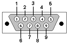
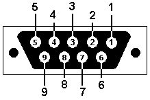
| View - looking into Male connector | View - looking into Female connector |
 |  |
| Pin No. | Name | Dir | Notes/Description |
|---|---|---|---|
| 1 | DCD | IN | Data Carrier Detect. Raised by DCE when modem synchronized. |
| 2 | RD | IN | Receive Data (a.k.a RxD, Rx). Arriving data from DCE. |
| 3 | TD | OUT | Transmit Data (a.k.a TxD, Tx). Sending data from DTE. |
| 4 | DTR | OUT | Data Terminal Ready. Raised by DTE when powered on. In auto-answer mode raised only when RI arrives from DCE. |
| 5 | SGND | - | Ground |
| 6 | DSR | IN | Data Set Ready. Raised by DCE to indicate ready. |
| 7 | RTS | OUT | Request To Send. Raised by DTE when it wishes to send. Expects CTS from DCE. |
| 8 | CTS | IN | Clear To Send. Raised by DCE in response to RTS from DTE. |
| 9 | RI | IN | Ring Indicator. Set when incoming ring detected - used for auto-answer application. DTE raised DTR to answer. |
Achievable Distances
The maximum distance that RS-232 can go varies depending on Baud Rate and also the capacitance of the wire itself. Texas Instruments states that RS-232 maximum cable length is 50 feet, or the cable length equal to a capacitance of 2500 pF. Depending on the cable such as Category 5 Twisted pair the maximum achievable distance at 19200 is 157 feet.
Here is a chart showing theoretical limits as various data rates for RS-232 cable length according to Texas Instruments.
| Baud rate | Maximum cable length (ft) |
|---|---|
| 19200 | 50 |
| 9600 | 500 |
| 4800 | 1000 |
| 2400 | 3000 |
Advantages
RS-232 is without doubt the best known interface, because this serial interface is implemented on almost all computers available today.
Disadvantages
One of the main problems with RS-232 is the lack of immunity for noise on the signal lines.
However RS-232 suffers from three main problems:
- 1) it requires multiple ground points and can create potential ground loops.
- 2) it picks up noise easily and
- 3) it allows only short communication distances.
In order to overcome some of these issues RS-422 or RS-485 is the preferred choice.
Interfacing to Microcontrollers
In order for RS232 to communicate with a Microcontroller such as a Pic16f88 or Atmel, level conversion must first be done because of the voltage levels on TTL is 5 Vdc max and normal RS232 far exceeds voltage limitations and damage will occur.
Devices such as a MAX232 will make the necessary voltage conversion possible for communication to and from TTL devices.