Renard 64XC Construction: Difference between revisions
No edit summary |
|||
| (6 intermediate revisions by 3 users not shown) | |||
| Line 35: | Line 35: | ||
|- | |- | ||
| | | | ||
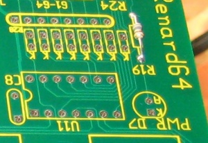
* Install one (1) 330 ohm resistor R19. Make sure that the resistors have a value of | * Install one (1) 330 ohm resistor R19. Make sure that the resistors have a value of 330 ohms [orange/orange/brown/gold]. | ||
|| [[Image:Renard 64XC R19 Install.jpg | 300px]] | || [[Image:Renard 64XC R19 Install.jpg | 300px]] | ||
|- | |- | ||
| Line 44: | Line 44: | ||
| | | | ||
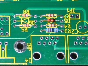
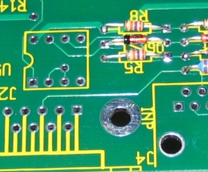
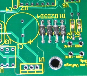
* Install zener diode D5. The diode must be installed correctly. The diode should have a black stripe on the orange/red body. Make sure that this stripe lines up with the stripe on the PCB silkscreen. | * Install 4.3v zener diode D5. The diode must be installed correctly. The diode should have a black stripe on the orange/red body. Make sure that this stripe lines up with the stripe on the PCB silkscreen. | ||
|| [[Image:Renard 64XC D5 Install.jpg | 300px]] | || [[Image:Renard 64XC D5 Install.jpg | 300px]] | ||
|- | |- | ||
| | | | ||
* Install zener diode D6. The diode must be installed correctly. The diode should have a black stripe on the orange/red body. Make sure that this stripe lines up with the stripe on the PCB silkscreen. | * Install 9.1v zener diode D6. The diode must be installed correctly. The diode should have a black stripe on the orange/red body. Make sure that this stripe lines up with the stripe on the PCB silkscreen. | ||
|| [[Image:Renard 64XC D6 Install.jpg | 300px]] | || [[Image:Renard 64XC D6 Install.jpg | 300px]] | ||
|- | |- | ||
| Line 80: | Line 80: | ||
|- | |- | ||
| | | | ||
* Install eight (8) 0.1uF capacitors C3-C10. These capacitors are not polarized so the orientation is not critical. The | * Install eight (8) 0.1uF capacitors C3-C10. These capacitors are not polarized so the orientation is not critical. The capacitor leads are already formed. However, sometimes they do not match the PCB holes exactly. Bend the leads as required to insert them into the PCB holes. Then, bend the leads back slightly to hold the capacitor in place. Solder and trim the leads the same as the resistors. | ||
|| [[Image:Renard 64XC C3-C10 Install.jpg | 300px]] | || [[Image:Renard 64XC C3-C10 Install.jpg | 300px]] | ||
|- | |- | ||
| Line 92: | Line 92: | ||
|- | |- | ||
| | | | ||
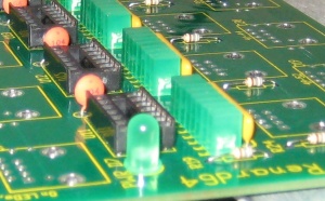
* Install the Power LED, D7. The LEDs are polarized and must be installed with the proper orientation. The long lead is the anode and must be placed in the round solder pad that is marked with an "A". The flat side of the LED (the short lead side) goes in the square pad marked with a "K". This is exactly opposite of the Channel LEDs in the | * Install the Power LED, D7. The LEDs are polarized and must be installed with the proper orientation. The long lead is the anode and must be placed in the round solder pad that is marked with an "A". The flat side of the LED (the short lead side) goes in the square pad marked with a "K". This is exactly opposite of the Channel LEDs in the previous step! Bend back the leads slightly as done with the resistors. Solder one lead and check from proper alignment. Then, solder the other lead and trim off the excess. | ||
|| [[Image:Renard 64XC Power LED D7 Install.jpg | 300px]] | || [[Image:Renard 64XC Power LED D7 Install.jpg | 300px]] | ||
|- | |- | ||
| Line 120: | Line 120: | ||
|- | |- | ||
| | | | ||
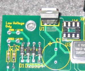
* Install the voltage regulator U1. The voltage regulator must be installed correctly. The voltage regulator's tab/heat sink must be aligned with wider line of the PCB silkscreen outline (facing outwards to the PCB edge). Insert the component and then flip the board over. Solder one pin...then flip the board back over and check for alignment. Simply reheat the joint and position the regulator so that | * Install the voltage regulator U1. The voltage regulator must be installed correctly. The voltage regulator's tab/heat sink must be aligned with wider line of the PCB silkscreen outline (facing outwards to the PCB edge). Insert the component and then flip the board over. Solder one pin...then flip the board back over and check for alignment. Simply reheat the joint and position the regulator so that it is square to the board. Solder the other two leads and trim off the excess. | ||
|| [[Image:Renard 64XC U1 Install.jpg| 300px]] | || [[Image:Renard 64XC U1 Install.jpg| 300px]] | ||
|- | |- | ||
| Line 133: | Line 133: | ||
|- | |- | ||
| | | | ||
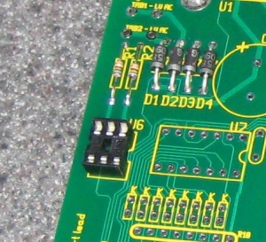
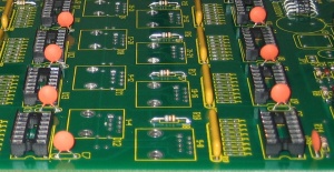
* Install the H11AA1 optocoupler | * Install the H11AA1 optocoupler U6. | ||
|- | |- | ||
| | | | ||
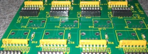
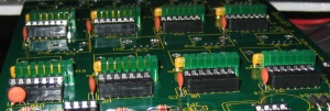
* Install eight (8) PIC microcontrollers U7-U14. The PICs need to be programmed with the appropriate firmware before installation. More info on programming PICs can be found [http://www.doityourselfchristmas.com/forums/showpost.php?p=3346&postcount=1 here.] | * Install eight (8) PIC microcontrollers U7-U14. The PICs need to be programmed with the appropriate firmware before installation. More info on programming PICs can be found [http://www.doityourselfchristmas.com/forums/showpost.php?p=3346&postcount=1 here.] | ||
|- | |- | ||
| | | | ||
* Install two (2) RS232/RS485 Interface ICs U4 & U5. | * Install two (2) RS232/RS485 Interface ICs U4 & U5. | ||
|- | |- | ||
| | | | ||
* OPTIONAL: Install a heat sink (PN# 532-577102B00) on voltage regulator U1. The mounting hardware and heat transfer compound are not included in the BOM since any common hardware can be used to attach the heat sink. If you don't have any heat transfer compound handy, you can use Mouser PN# 532-249. | * OPTIONAL: Install a heat sink (PN# 532-577102B00) on voltage regulator U1. The mounting hardware and heat transfer compound are not included in the BOM since any common hardware can be used to attach the heat sink. If you don't have any heat transfer compound handy, you can use Mouser PN# 532-249. | ||
|- | |- | ||
|} | |} | ||
| Line 154: | Line 150: | ||
<center>'''Completed Renard 64XC'''</center> | <center>'''Completed Renard 64XC'''</center> | ||
Latest revision as of 03:59, 2 October 2012
Board Assembly
- Note: Pictures are being added daily and the sequence is changing based on an actual assembly.
- The following sequence of steps is by no means the only way to assemble the Renard 64. It is simply a suggested order of assembly. Many builders have varied opinions on what the order should be. In general, you start with the "shortest" items and work towards the tallest. This generally means that resistors are first and connectors are last but every board is different.
- A good temperature controlled soldering iron should be used for building the Renard 64. Try to get the smallest diameter rosin core solder you can find (either 60/40 or 63/37). PLEASE DO NOT USE LEAD FREE SOLDER!! This takes special equipment and a very high skill set that few DIYers have. If you do use Lead Free Solder and have problems (which is VERY likely) please let us know when you ask for help. Lead Free Solder can look like a good joint but still be a problem.
- One safety note is prudent here. Solder is METAL (lead and tin)...In order to use it,it must be MELTED. HOT, Molten Metal can BURN! Also, metal leads get hot while soldering. So, any unprotected fingers that are being used to "hold" a component in place will be burned!! Painter's tape is one way of holding items down while the board is being flipped over. Another way is to use another unpopulated board or flat surface to allow the board to be flipped while keeping the components in place.
- NOTE: The part numbers referenced in the following instructions are those taken from the Renard 64 BOM.
| |
|
|
|
|
|
|
|
|
|
|
|
|
|
|
|
|
|
|
| |
|
|
|
|
|
|
| |
|
|
|
|
|
|
|
|
|
|
|
|
|
|
|
|
|
|
|
|
|
|
|
|
|
|
| |
| |
| |
| |
| |
| |