Ren-W Troubleshooting: Difference between revisions
Dirknerkle (talk | contribs) |
Dirknerkle (talk | contribs) |
||
| (4 intermediate revisions by the same user not shown) | |||
| Line 13: | Line 13: | ||
::* The 3.3 voltage regulator (U1) has the metal tab facing up, toward the JP2 header pins. On the Rev-6 board, the metal tab faces to the right, toward the C3 capacitor. | ::* The 3.3 voltage regulator (U1) has the metal tab facing up, toward the JP2 header pins. On the Rev-6 board, the metal tab faces to the right, toward the C3 capacitor. | ||
::* The electrolytic capacitor (C3) has the - stripe facing DOWN toward the LED, which means the + side is up toward the J2 jack. | ::* The electrolytic capacitor (C3) has the - stripe facing DOWN toward the LED, which means the + side is up toward the J2 jack. | ||
::* Capacitors C1, C2 | ::* Capacitors C1, C2, C4, C5 and C6 are essential to the stability of the MAX232 chip, and C3 is needed to help smooth out the 5vdc power. | ||
::* If using an electrolytic capacitor for C1, C2, C4, C5 or C6, be sure its polarity is correct | ::* If using an electrolytic capacitor for C1, C2, C4, C5 or C6, be sure its polarity is correct. | ||
::* The LED (D2) while not very clear in this photo, has the kathode (flat side) facing the mounting hole to its right. On the Rev-6 board, the flat side faces to the right, toward the U1 voltage regulator. | ::* The LED (D2) while not very clear in this photo, has the kathode (flat side) facing the mounting hole to its right. On the Rev-6 board, the flat side faces to the right, toward the U1 voltage regulator. | ||
::* Resistor R1 (33 ohms) is immediately below the MAX232 chip. The resistor has no polarity concerns. | ::* Resistor R1 (33 ohms) is immediately below the MAX232 chip. The resistor has no polarity concerns. | ||
| Line 75: | Line 75: | ||
::* Using 57600, 8 bits, Mark parity and 2 stop bits for daisy-chained Ren-W/controllers. Use 57,600, 8, N, 1 instead. | ::* Using 57600, 8 bits, Mark parity and 2 stop bits for daisy-chained Ren-W/controllers. Use 57,600, 8, N, 1 instead. | ||
== RS-485 Patch for Ren-W as a Transmitter at the PC == | == RS-485 Patch for Ren-W as a Transmitter at the PC - Pre-version 20100622 only == | ||
::NOTE: This patch applies ONLY to Ren-W boards prior to version 20100622, and it does not apply at all to the Rev-6 or Rev7 boards. | |||
:A better and more secure transmitter can be made by using only the -485 signal and allowing the Max232 chip to invert it before sending it to the XBee. The patch has been well-tested and is very easy to make. You probably will need to make the change only to one Ren-W board if you plan to use it as a transmitter direct from your PC instead of using the XBee Explorer board. Here's how: | :A better and more secure transmitter can be made by using only the -485 signal and allowing the Max232 chip to invert it before sending it to the XBee. The patch has been well-tested and is very easy to make. You probably will need to make the change only to one Ren-W board if you plan to use it as a transmitter direct from your PC instead of using the XBee Explorer board. Here's how: | ||
| Line 142: | Line 142: | ||
:::* Write the settings to the radio. | :::* Write the settings to the radio. | ||
:::* Make sure Vixen's com settings for the Renard plug-in is set to MARK parity and 2 stop bits also. | :::* Make sure Vixen's com settings for the Renard plug-in is set to MARK parity and 2 stop bits also. | ||
== What if I can't Figure It Out? == | |||
You can always send your Ren-W boards to Dirknerkle -- he'll be glad to check them out and fix whatever needs fixing. If you need to do this, just PM the dirk sometime for his address. Oh, and you'll want to send the XBee modules too, because he'll want to check everything out and test it. You'll get them back in perfect working order and his turnaround is super-fast. | |||
Latest revision as of 01:21, 2 July 2012
The Ren-W circuit board is a very simple design but good soldering technique is still extremely important.
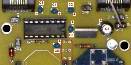
Voltage Measurements: three test points are just below pin 16 of the MAX232 chip/socket (circled in red):
Construction Mistakes
- The Ren-W board was designed for home-etching and thus has very generous traces and solder pads. Be certain that the following components are mounted on the board properly:
- The notch on the MAX232 chip faces to the right, toward the U1 voltage regulator.
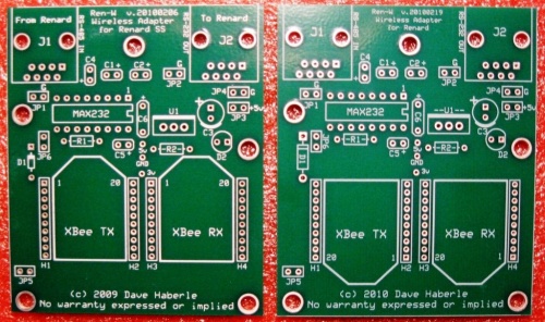
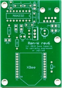
- The zener diode (D1) has the black stripe on the TOP, next to the JP6 header pins. On the Rev-6 board the diode stripe is on the BOTTOM.
- The 3.3 voltage regulator (U1) has the metal tab facing up, toward the JP2 header pins. On the Rev-6 board, the metal tab faces to the right, toward the C3 capacitor.
- The electrolytic capacitor (C3) has the - stripe facing DOWN toward the LED, which means the + side is up toward the J2 jack.
- Capacitors C1, C2, C4, C5 and C6 are essential to the stability of the MAX232 chip, and C3 is needed to help smooth out the 5vdc power.
- If using an electrolytic capacitor for C1, C2, C4, C5 or C6, be sure its polarity is correct.
- The LED (D2) while not very clear in this photo, has the kathode (flat side) facing the mounting hole to its right. On the Rev-6 board, the flat side faces to the right, toward the U1 voltage regulator.
- Resistor R1 (33 ohms) is immediately below the MAX232 chip. The resistor has no polarity concerns.
- Resistor R2 (1k ohms) is immediately below the U1 voltage regulator. The resistor has no polarity concerns.
- Be sure to observe the XBee module's orientation as printed on the board; remember that the standard board has the XBee pointing upward while the SMA board has the module pointing downward. If you have the standard board, DO NOT simply turn the module around to point downward for an XBee module with an SMA connector -- it will not work and you may damage the radio when power is applied!
Soldering Mistakes
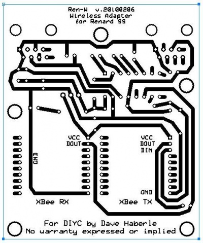
- When you study the underside (copper) side of the circuit board, a few things become readily apparent:
- Very few pins of the XBee radio modules are actually used; most are unused and serve only to hold the header sockets securely.
- The solder pads for the XBee headers are very small; accurate and careful soldering is a must to prevent solder bridges. A solder bridge could easily prevent the XBee radio from functioning properly and could damage it. Note the elongated pads for the XBee headers, too. These provide home etch boards will a larger soldering surface.
- Note that the cat5 jacks J1 and J2 include additional solder pads for pins that don't connect to anything. These are provided for home etch boards by providing additional soldering area and strength in holding the jacks to the board.
Cabling Mistakes
- The Ren-W does not need a special cable when connecting J1 or J2 to the Renard controller. A standard cat5 cable with standard pinouts should work fine. It's a good idea to keep this relatively short inside a controller box so that you don't end up with a coil of wire, which could affect transmission. Otherwise, the length of the cat5 cables connecting the Ren-W to the controller should be limited to 50 feet or less, the recommended maximum for RS-232 communications.
- When connecting a Ren-W directly to a computer's -485 output to be a "transmit only" unit, remember that the Ren-W takes input only on pin 4 of J1 connector and ground is made on pins 1-2. You may need to make a special cable by connecting -485 to pin 4 before plugging it into J1 of the Ren-W. Ren-W does not use pin 5.
- If the Ren-W locks up unexpectedly when connected to a PC in transmit only mode and only unplugging power temporarily restores operations, check the input voltage of the RS-485 line connecting into J1 of the Ren-W; it should be the -485 line.
- The Rev-6 version of the Ren-W board requires that JP2 on an SS8, SS16 or SS24 sontroller be open and not shunted. This is because Rev-6 has only one RJ45 jack, and it uses a different physical connection point to the SS board. (JP2 is the termination resistor on an SS controller)
Interaction With other Wi-Fi Devices
- Xbee radios operate in the 2.4ghz frequency spectrum, the same spectrum as your wi-fi router or wireless access point. It is possible that you may encounter interaction between the two if the wi-fi device is in close proximity to a receiving XBee radio. The symptom is misfires or it may even appear to be randomly responsive. For example, a wireless laptop with a live, wireless connection could negatively influence the reception of a nearby controller with a Ren-W, or a wireless webcam placed near a remote controller with a Ren-W could easily influence that Ren-W's ability to discriminate the Xbee control signal if the webcam's transmission is too strong.
- Possible solution: Wireless routers, webcams, access points (etc.) usually have the option to use a "channel" as the primary communicating link. XBee radios also have a channel setting and depending on whether it's a regular Xbee or an XBPro, the channel options may differ. The default XBee channel is channel "C." Try changing the XBee radios to a different channel and see if the conflicts go away. Note that the channel setting must be made on ALL XBees that are to communicate with one another.
Interaction with FM Radio Transmitter Antenna
- Even though normal broadcast FM is in the megahertz frequency range while XBee radios communicate in the gigahertz range, it's possible that when the XBee transmitting radio is very close to the FM transmitter's antenna, some interaction may occur causing either distortion in the FM radio signal or possibly some interference with the XBee if the FM transmitter is very powerful. It's probably best to keep them separated by a few feet if possible.
Using Common Sense
- Ren-W's will communicate best when there is a direct line-of-sight between the transmitter and the receiver. It's just obvious common sense to place the transmitting antenna in such a place where it will have the fewest things between it and the receiving units. If your receiving Ren-Ws are in the front yard, then putting the transmitter in the back yard doesn't make a lot of sense and you'll likely encounter misfires because of it.
- When you place your receiving unit/controller on the ground, or near your display, place it so that the antenna is closer to the transmitting antenna. If the antenna is inside the controller's case and in a corner, place the controller so that corner is the closest corner to the transmitting antenna. Just good common sense.
- If your transmitting antenna is vertical, then when you position your controllers/receiving Ren-Ws, place them so that their antennae are parallel to the transmitter so as to maximize the reception of the radio waves. In some cases, the units may be so close to the transmitting antenna that it doesn't matter, and that's fine, but the further away you get, the more important it will be to minimize misfires.
- If a receiving unit is quite distant or has many trees, bushes, swingsets or other things in the way, consider using putting an external antenna on the receiving unit. It will be vastly superior to using any of the XBee's built-in antennas and can greatly help reduce misfires. Again, it's common sense -- try to get the antennae so there are few impediments between them.
- Understand that there will be misfires with Ren-W, but there will be fewer of them if you follow these common sense guidelines. Remember, the Renard protocol is asynchronous -- it sends out only and it doesn't look for any return confirmation that a packet that was sent was actually delivered. This is by design because if communication was poor, there would be a lot slower transfer of data to your controllers because of all the retries going on and your lights would always lag behind your music. Hence, Renard is asynchronous. So is Ren-W for the very same reason. Therefore, to minimize misfires, you need to do everything in your power to allow the best communication between the transmitter and the receivers as you possibly can.
Other Easy Mistakes
- Plugging the XBee module into the wrong side of the board for the kind of function the board is to do. Remember:
- A receive-ONLY Ren-W has the XBee mounted in the RX (right) side and no jumper is on JP5. The cat5 cable is plugged into J2 and into the J2 socket of the Renard SS controller (the controller's RS-232 IN port)
- A transmit-ONLY Ren-W has the XBee mounted in the TX (left) side and no jumper is on JP5. The cat5 cable is plugged into J1 and into the J1 socket of the Renard SS controller (the controller's RS-485 OUT port).
- An E-Mode Repeater has is exactly the same as a transmit-only board but JP5 is jumpered instead. Cat5 cables connect both jacks J1 and J2 to the Renard controller's RS-485 OUT and RS-232 IN ports respectively.
- Connecting J1 to the Renard controller for a receive-only Ren-W won't work because a receive-only Ren-W uses J2 for the cat5.
- Connecting J2 to the Renard controller for a transmit-only Ren-W won't work because a transmit-only Ren-W uses J1 for the cat5.
- Misconfiguring the 16-bit address of an XBee module.
- Misconfiguring the LOW address of an XBee module.
- Setting the destination address of an XBee module to the wrong address. (This is a hard one to find!)
- Setting one radio to transmit to a specific destination XBee but not having the destination XBee in the test.
- Changing the PANID to the wrong value; remember, only radios with the same PANID can communcate with one another.
- Forgetting to set the Renard controller to accept RS-232 data.
- Mounting the Ren-W so the antenna is too close to a transformer or even a triac on the Renard controller can cause erratic transmission and/or reception behavior.
- If using the Ren-W to transmit control commands to a Ren-C/595 or Ren-C/Grinch controller, be sure that the cat5 cable that goes from J2 of the Ren-W to the Rs-IN jack of the Ren-C has a choke core balun affixed to it (Radio Shack part# 273-0069). You might also coil the cat5 cable into 4 or 5 loops approx 5" across if the balun alone doesn't solve the problem. This will reduce the amount of EMI/RFI that the XBee radio produces, which the ren-C may mistakenly see as serial input and cause framing errors. It's also possible that the framing error LED on a Ren-C may light even though everything is functioning properly. This is likely due to some of the XBee's EMI getting through anyway and is probably not a critical issue.
- Unplugging or plugging-in an XBee module while the Ren-W board is powered up. This can adversely affect and XBee module, and it's just good practice to remove power from it before unplugging anything.
- Resetting an XBee module back to its default specs (an option in the XCTU software) but forgetting to reset the baud rate back to 57600 before putting it back in a Ren-W socket.
- Using 57600, 8 bits, Mark parity and 2 stop bits for daisy-chained Ren-W/controllers. Use 57,600, 8, N, 1 instead.
RS-485 Patch for Ren-W as a Transmitter at the PC - Pre-version 20100622 only
- NOTE: This patch applies ONLY to Ren-W boards prior to version 20100622, and it does not apply at all to the Rev-6 or Rev7 boards.
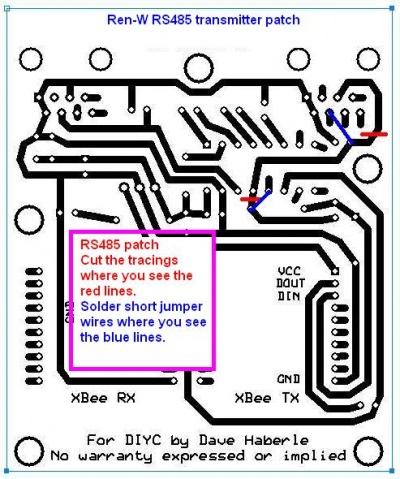
- A better and more secure transmitter can be made by using only the -485 signal and allowing the Max232 chip to invert it before sending it to the XBee. The patch has been well-tested and is very easy to make. You probably will need to make the change only to one Ren-W board if you plan to use it as a transmitter direct from your PC instead of using the XBee Explorer board. Here's how:
- Cut the bottom copper tracing in two places, shown as RED LINES in the picture.
- Solder short jumper wires were indicated in BLUE LINES in the picture.
- When done, the -485 line will be sent to the Max232 where it will be inverted and sent to the XBee's input via the zener diode, which will limit the voltage to 3.3v, the maximum prescribed for the XBee.
Transmission Test
- This procedure gives you a chance to see what the Renard data looks like to a controller and it serves ad a terrific way to test a transmitting Ren-W board as well as a receiving XBee module to make sure they're using the same communication parameters.
- Set up a Ren-W in transmit only mode (XBee in the TX side, standard cat5 cable connecting from the RS-OUT jack of the Renard to the RS-IN jack of the Ren-W, Ren-W powered on.)
- Plug your computer's serial output into the Renard controller's serial IN. Either RS-232 or RS-485 is fine. Just connect it to your computer's serial port as you would normally.
- Use an USB XBee Explorer programmer board with an XBee radio plugged into it as the "receiver."
- Plug the Explorer board into the computer
- Start up the XCTU software, connect to the XBee radio.
- Open the TERMINAL window, select the SHOW HEX button.
- Leave the screen open so you can view it.
- Start up Vixen
- Define a new profile with twice as many channels as the Renard controller you're using. If it's an SS16, then create a 32-channel profile using the Renard Dimmer (modified) plugin.
- Open a new sequence and link it to the new profile you just created.
- Make Vixen's screen smaller so you can see both Vixen and the XCTU Terminal screen at the same time.
- Open Vixen's channel test feature. When it appears on the screen, your should see a block of HEX information pop into the XCTU screen's window. You'll see a 7E 80 sequence followed by as many pairs of zeros as half of your total channel count. If you have defined a 32 channel profile and are using an SS16, then you'll see sixteen pairs of zeros.
- On Vixen's channel test box, click the SELECT ALL button. You'll see the XCTU screen fill with another 7E 80 followed by pairs of FFs, representing "all on" for all the channels. Click the UNSELECT ALL button and the screen will return to zeros.
- Use the slider bar when the lights are "all on" and watch the XCTU screen fill with data. Each slider bar change sends a whole set of data for all channels. You'll be amazed how much data is processed, and how quickly, too.
- You can play an actual sequence in this way, too, and watch all the data flow through to what the transmitting Ren-W board thinks is another Ren-W, but is actually just an XBee radio. You'll be able to see patterns emerge after a while.
Renard/XBee Timing Issue and Channels 57-64
- An issue has been reported and reproduced on the Ren64 whereby at 57600 baud, channels 57-64 act inconsistently. They seem to work okay with the ALL CHANNEL test and appear to work okay with most blinky-type activity, but in slower testing, some channels may not come on at all. It's important to know that the problem is not with the Renard boards or the Renard firmware: the problem is that the XBee's communication speed is a bit fast and also that certain versions of the XBee firmware have a bug in the serial settings. Changing the firmware and XBee radio to operate at 38400 baud completely solves the problem. However, this also lowers the total number of channels that can be controlled on a single com port at that speed. Another solution is to use only channels 1-56 on the Ren64 controller and continue to operate at 57600, which effectively provides for up to 254 usable channels out of the suggested maximum 286 when sequencing at 50ms. Two additional solutions are available: one is a combination hardware/firmware modification on the Ren64; the second is a firmware modification on the XBee radio coupled with a changed Vixen settiong. Be sure to read BOTH solutions before you start hacking your board! First, the Hardware/Firmware modification of the Ren64 board:
SOLUTION #1- Hardware/Firmware modification on the Ren64 board - (thanks to tweist!)
- Disconnect pin 5 of the U14 pic, and connect a jumper wire between pin5 and pin 1 of U5 (the rightmost ST485BN chip). Then reflash the firmware on the U14 pic with start address 4.
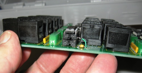
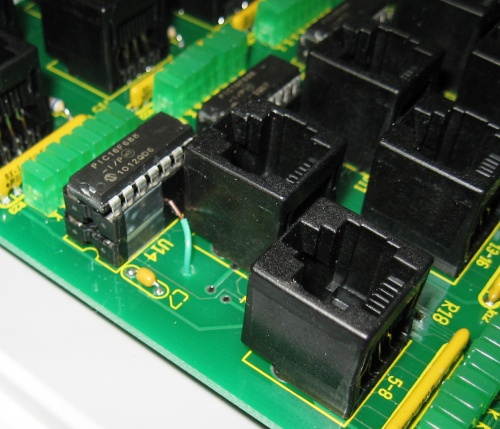
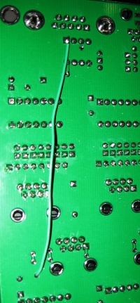
- Here's a slick way to do it that won't compromise any traces on the Ren64 board:
- 4. Remember to flash the U14 pic with start address firmware set with start_addr 4.
SOLUTION #2 - XBee Firmware Upgrade/Vixen 2 stop bits
- Unsolvable communication issues have been reported by users who have XBee radios that use XBee firmware version 10CD. It is possible that other versions also have a similar problem, but upgrading the XBee firmware to version 10E6 apparently solves the issue when you set the XBee firmware's parity setting to 3-MARK PARITY. The other setting change is to set your Renard plugin com settings to 57600, 8 data bits and 2 stop bits. However, one of the other issues is that XBee version 10CD is quite cantankerous and generally doesn't upgrade itself. Here's the solution to that:
- Be sure your XCTU software has version 10E6 available in the version box. XCTU has a button option to check for new versions on the Digi web site.
- Restore the XBee radio to the factory default settings by clicking the RESTORE button.
- Change your XTCU settings to the default 9600 baud, 8 data bits, no parity and 1 stop bit and load the XBee configuration. Verify that it has version 10CD. (If you don't have 10CD, you can use this procedure to update it to 10E6 anyway.)
- Check the box to "Always update firmware"
- Choose version 10A5 in the version window. (Yes, you have to DOWNGRADE it first.)
- Click the WRITE button to write the changes, initialize the radio and reprogram it with 10A5 firmware.
- (Do the next two steps very quickly!) When done, uplug the XBee radio so it has no power.
- Re-plug in the XBee, open it again and read the settings.
- Make sure the "Always update firmware" box is checked.
- Choose version 10E6 in the version window.
- Click the WRITE button again.
- When finished, unplug the radio again to remove power, then plug it back in and read the settings again. You should see version 10E6 in the version box.
- Make the normal changes as already suggested (PanID, No-Acks, 57600 baud, packetization timeout 0).
- Change the PARITY setting to 3-MARK PARITY
- Write the settings to the radio.
- Make sure Vixen's com settings for the Renard plug-in is set to MARK parity and 2 stop bits also.
What if I can't Figure It Out?
You can always send your Ren-W boards to Dirknerkle -- he'll be glad to check them out and fix whatever needs fixing. If you need to do this, just PM the dirk sometime for his address. Oh, and you'll want to send the XBee modules too, because he'll want to check everything out and test it. You'll get them back in perfect working order and his turnaround is super-fast.
Additional Ren-W Links
