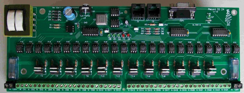
Renard 64XC Construction: Difference between revisions
No edit summary |
|||
| Line 15: | Line 15: | ||
* Install two 750 ohm resistors R1 & R2. Make sure that the resistors have a value of 750 ohms [violet/green/brown/gold stripes]. These resistors have no polarity to worry about. | * Install two 750 ohm resistors R1 & R2. Make sure that the resistors have a value of 750 ohms [violet/green/brown/gold stripes]. These resistors have no polarity to worry about. | ||
<!--|| [[Image:Wiki - Renard SS24 Assembly Step03.jpg | 200px]]--> | <!--|| [[Image:Wiki - Renard SS24 Assembly Step03.jpg | 200px]]--> | ||
|- | |- | ||
| | | | ||
| Line 29: | Line 25: | ||
|- | |- | ||
| | | | ||
* Install three (3) 27K ohm resistors R5, R8, and | * Install three (3) 27K ohm resistors R5, R8, and R14. Make sure that the resistors have a value of 27K ohms [red/violet/orange/gold stripes]. | ||
<!--|| [[Image:Wiki - Renard SS24 Assembly Step06.jpg | 200px]]--> | <!--|| [[Image:Wiki - Renard SS24 Assembly Step06.jpg | 200px]]--> | ||
|- | |- | ||
| | | | ||
* Install | * Install one (1) 300 ohm resistors R19. Make sure that the resistors have a value of 330 ohms [???/???/???/gold]. | ||
<!--|| [[Image:Wiki - Renard SS24 Assembly Step09.jpg | 200px]]--> | <!--|| [[Image:Wiki - Renard SS24 Assembly Step09.jpg | 200px]]--> | ||
|- | |- | ||
| | | | ||
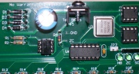
* Install four diodes D1 thru D4. The diodes will have a silver/grey stripe on a black body. Make sure that this stripe lines up with the stripe on the PCB silk screen | * Install four diodes D1 thru D4. The diodes will have a silver/grey stripe on a black body. Make sure that this stripe lines up with the stripe on the PCB silk screen. | ||
<!--|| [[Image:Wiki - Renard SS24 Assembly Step02.jpg | 200px]]--> | <!--|| [[Image:Wiki - Renard SS24 Assembly Step02.jpg | 200px]]--> | ||
|- | |- | ||
| Line 53: | Line 45: | ||
|- | |- | ||
| | | | ||
* Install | * Install eight (8) 0.1uF capacitors C3-C10. These capacitors are not polarized so the orientation is not critical. | ||
<!--|| [[Image:Wiki - Renard SS24 Assembly Step11.jpg | 200px]]--> | <!--|| [[Image:Wiki - Renard SS24 Assembly Step11.jpg | 200px]]--> | ||
|- | |- | ||
| Line 60: | Line 52: | ||
|- | |- | ||
| | | | ||
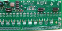
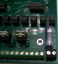
* Install the eight (8) 330 ohm resistor networks | * Install the eight (8) 330 ohm resistor networks R10-R13 and R20-R23. The resistor network should have a dot on it to indicate pin 1. Insert pin 1 of the resistor network into the square solder pad. | ||
<!--|| [[Image:Wiki - Renard SS24 Assembly Step12.jpg | 200px]]--> | <!--|| [[Image:Wiki - Renard SS24 Assembly Step12.jpg | 200px]]--> | ||
|- | |- | ||
| | | | ||
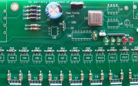
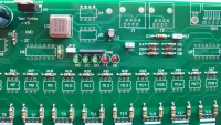
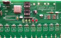
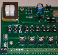
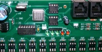
* Install | * Install the Power LED, D7. The LEDs are polarized and must be installed with the proper orientation. The short lead is the cathode and must be placed in the square solder pad. | ||
* Install | |- | ||
|| [[Image:Wiki - Renard SS24 Assembly Step13.jpg | 200px]] | | | ||
* Install sixty four (64) Green Channel LEDs. The LEDs are polarized and must be installed correctly. The short lead is the cathode and must be placed in the square solder pad. This is marked on the silkscreen with a "K". | |||
<!--|| [[Image:Wiki - Renard SS24 Assembly Step13.jpg | 200px]]--> | |||
|- | |- | ||
| | | | ||
Revision as of 06:03, 13 August 2010
Board Assembly
- The following sequence of steps is by no means the only way to Assembly the Renard 64. It is simply a suggested order of assembly. Many will have varied opinions on what the order should be.
- NOTE: The part numbers referenced in the following instructions are those taken from the Renard 64 BOM.
| |
| |
| |
| |
| |
| |
| |
| |
| |
| |
| |
| |
| |
| |
|
|
|
|
|
|
|
|
|
|
|

|
| |
|
|
|
|
|

|
|

|
|
|
|

|
|
|
|
|
|
|
| |
| |
|
|
|

|
|
|
|

|
|
|
|
|

