Renard 64XC Construction: Difference between revisions
| Line 7: | Line 7: | ||
:A good temperature controlled soldering iron should be used for building the Renard 64. Try to get the smallest diameter rosin core solder you can find (either 60/40 or 63/37). DO NOT USE LEAD FREE SOLDER!! This takes special equipment and a very high skill set that few DIYers have. If you do use Lead Free Solder and have problems (which is VERY likely) please let us know when you ask for help. Lead Free Solder can look like a good joint but still not be electrically conductive. | :A good temperature controlled soldering iron should be used for building the Renard 64. Try to get the smallest diameter rosin core solder you can find (either 60/40 or 63/37). DO NOT USE LEAD FREE SOLDER!! This takes special equipment and a very high skill set that few DIYers have. If you do use Lead Free Solder and have problems (which is VERY likely) please let us know when you ask for help. Lead Free Solder can look like a good joint but still not be electrically conductive. | ||
One safety note is prudent here. Solder is METAL (lead and tin)...In order to use it,it must be MELTED. HOT, Molten Metal can BURN! Also, metal leads get hot while soldering. So, any unprotected fingers that are being used to "hold" a component in place will be burned!! Painter's tape is one way of holding items down while the board is being flipped over. Another way is to use another unpopulated board or flat surface to allow the board to be flipped while keeping the components in place. | :One safety note is prudent here. Solder is METAL (lead and tin)...In order to use it,it must be MELTED. HOT, Molten Metal can BURN! Also, metal leads get hot while soldering. So, any unprotected fingers that are being used to "hold" a component in place will be burned!! Painter's tape is one way of holding items down while the board is being flipped over. Another way is to use another unpopulated board or flat surface to allow the board to be flipped while keeping the components in place. | ||
:'''NOTE:''' The part numbers referenced in the following instructions are those taken from the [[Renard_64XC#Bill_of_Materials | Renard 64 BOM]]. | :'''NOTE:''' The part numbers referenced in the following instructions are those taken from the [[Renard_64XC#Bill_of_Materials | Renard 64 BOM]]. | ||
| Line 35: | Line 35: | ||
|- | |- | ||
| | | | ||
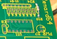
* Install one (1) | * Install one (1) 680 ohm resistor R19. Make sure that the resistors have a value of 330 ohms [orange/orange/brown/gold]. | ||
|| [[Image:Renard 64XC R19 Install.jpg | 200px]] | |||
|- | |||
| | |||
* Install the eight (8) 680 ohm resistor networks R10-R13 and R20-R23. The resistor network should have a dot on it to indicate pin 1. Insert pin 1 of the resistor network into the square solder pad. Sometimes a piece of tape is used to hold the resistor network in place while soldering the first pin. Once this is done, check the resistor network to ensure that it is straight and plumb to the board. If not, re-heat the first lead and reposition as required. Then, solder the other 7 pins. The leads do not have to be trimmed for this component. | |||
|| [[Image:Renard 64XC R10-13 R20-23 Install.jpg | 200px]] | |||
|- | |- | ||
| | | | ||
| Line 56: | Line 60: | ||
|<center>'''INSTALLATION NOTE:''' </center> | |<center>'''INSTALLATION NOTE:''' </center> | ||
<blockquote>The following resistor network is a "bussed" type resistor network. This means that the seven (7) resistor components (pins 2-8) are all connected in a common buss to pin 1. Installing the resistor network backwards will cause a multitude of malfunctions. So please take the time to make sure they are installed correctly.</blockquote> | <blockquote>The following resistor network is a "bussed" type resistor network. This means that the seven (7) resistor components (pins 2-8) are all connected in a common buss to pin 1. Installing the resistor network backwards will cause a multitude of malfunctions. So please take the time to make sure they are installed correctly.</blockquote> | ||
|- | |- | ||
| | | | ||
Revision as of 00:47, 27 August 2010
Board Assembly
- Note: Pictures will be added as soon as they are available
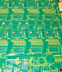
- The following sequence of steps is by no means the only way to Assembly the Renard 64. It is simply a suggested order of assembly. Many builders have varied opinions on what the order should be. In general, you start with the "shortest" items and work towards the tallest. This generally means that resistors are first and connectors are last but every board is different.
- A good temperature controlled soldering iron should be used for building the Renard 64. Try to get the smallest diameter rosin core solder you can find (either 60/40 or 63/37). DO NOT USE LEAD FREE SOLDER!! This takes special equipment and a very high skill set that few DIYers have. If you do use Lead Free Solder and have problems (which is VERY likely) please let us know when you ask for help. Lead Free Solder can look like a good joint but still not be electrically conductive.
- One safety note is prudent here. Solder is METAL (lead and tin)...In order to use it,it must be MELTED. HOT, Molten Metal can BURN! Also, metal leads get hot while soldering. So, any unprotected fingers that are being used to "hold" a component in place will be burned!! Painter's tape is one way of holding items down while the board is being flipped over. Another way is to use another unpopulated board or flat surface to allow the board to be flipped while keeping the components in place.
- NOTE: The part numbers referenced in the following instructions are those taken from the Renard 64 BOM.
| |
|
|
|
|
|
|
|

|
|
|
|
|
| |
| |
| |
| |
| |
| |
| |
| |
| |
| |
| |
| |
| |
| |
| |
| |
| |
| |
| |
| |
| |
| |
| |
| |
| |
| |