|
|
| Line 16: |
Line 16: |
| | | | | |
|
| |
|
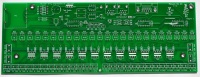
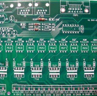
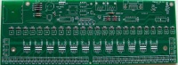
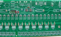
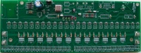
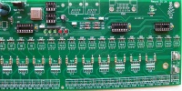
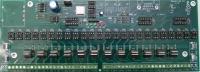
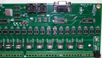
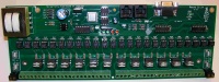
| * Start by checking the PCB over for any obvious production faults. Check for traces that end abruptly or have cracks/breaks in them. Also check that all holes are clear. | | * '''1''' - Start by checking the PCB over for any obvious production faults. Check for traces that end abruptly or have cracks/breaks in them. Also check that all holes are clear. |
| || [[Image:Wiki - Renard SS24 PCB.jpg | 200px]] | | || [[Image:Wiki - Renard SS24 PCB.jpg | 200px]] |
| |- | | |- |
| | | | | |
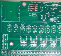
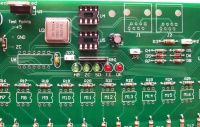
| * '''1''' - Install four diodes D1 thru D4 (PN# 625-1N5817-E3). The diodes will have a silver/grey stripe on a black body. Make sure that this stripe lines up with the stripe on the PCB silk screen (to the left). | | * '''2''' - Install four diodes D1 thru D4 (PN# 625-1N5817-E3). The diodes will have a silver/grey stripe on a black body. Make sure that this stripe lines up with the stripe on the PCB silk screen (to the left). |
| || [[Image:Wiki - Renard SS24 Assembly Step02.jpg | 200px]] | | || [[Image:Wiki - Renard SS24 Assembly Step02.jpg | 200px]] |
| |- | | |- |
| | | | | |
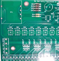
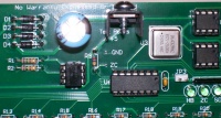
| * '''2''' - Install two 750 ohm resistors R1 & R2 (PN# 291-750-RC). Make sure that the resistors have a value of 750 ohms (violet/green/brown/gold stripes). These resistors have no polarity to worry about. | | * '''3''' - Install two 750 ohm resistors R1 & R2 (PN# 291-750-RC). Make sure that the resistors have a value of 750 ohms (violet/green/brown/gold stripes). These resistors have no polarity to worry about. |
| || [[Image:Wiki - Renard SS24 Assembly Step03.jpg | 200px]] | | || [[Image:Wiki - Renard SS24 Assembly Step03.jpg | 200px]] |
| |- | | |- |
| | | | | |
| * '''3''' - Install the 120 ohm resistor R3 (PN# 291-120-RC). Make sure that the resistor has a value of 120 ohms (brown/red/brown/gold stripes). This resistor have no polarity to worry about. | | * '''4''' - Install the 120 ohm resistor R3 (PN# 291-120-RC). Make sure that the resistor has a value of 120 ohms (brown/red/brown/gold stripes). This resistor have no polarity to worry about. |
| || [[Image:Wiki - Renard SS24 Assembly Step04.jpg | 200px]] | | || [[Image:Wiki - Renard SS24 Assembly Step04.jpg | 200px]] |
| |- | | |- |
| | | | | |
| * '''4''' - Install two 1K ohm resistors R4, R7 (PN# 299-1K-RC). Make sure that the resistors have a value of 1K ohm (brown/black/red/gold stripes). These resistors have no polarity to worry about. | | * '''5''' - Install two 1K ohm resistors R4, R7 (PN# 299-1K-RC). Make sure that the resistors have a value of 1K ohm (brown/black/red/gold stripes). These resistors have no polarity to worry about. |
| || [[Image:Wiki - Renard SS24 Assembly Step05.jpg | 200px]] | | || [[Image:Wiki - Renard SS24 Assembly Step05.jpg | 200px]] |
| |- | | |- |
| | | | | |
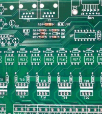
| * '''5''' - Install three 27K ohm resistors R5, R8, R9 (PN# 299-27K-RC). Make sure that the resistors have a value of 27K ohms (red/violet/orange/gold stripes). These resistors have no polarity to worry about. | | * '''6''' - Install three 27K ohm resistors R5, R8, R9 (PN# 299-27K-RC). Make sure that the resistors have a value of 27K ohms (red/violet/orange/gold stripes). These resistors have no polarity to worry about. |
| || [[Image:Wiki - Renard SS24 Assembly Step06.jpg | 200px]] | | || [[Image:Wiki - Renard SS24 Assembly Step06.jpg | 200px]] |
| |- | | |- |
| | | | | |
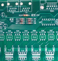
| * '''6''' - Install zener diode D5 (PN# 78-1N5229B). The diode must be installed correctly. The diode should have a black stripe on the orange/red body. Make sure that this stripe lines up with the stripe on the PCB silkscreen (to the left). | | * '''7''' - Install zener diode D5 (PN# 78-1N5229B). The diode must be installed correctly. The diode should have a black stripe on the orange/red body. Make sure that this stripe lines up with the stripe on the PCB silkscreen (to the left). |
| || [[Image:Wiki - Renard SS24 Assembly Step07.jpg | 200px]] | | || [[Image:Wiki - Renard SS24 Assembly Step07.jpg | 200px]] |
| |- | | |- |
| | | | | |
| * '''7''' - Install zener diode D6 (PN# 78-1N5239B). The diode must be installed correctly. The diode should have a black stripe on the orange/red body. Make sure that this stripe lines up with the stripe on the PCB silkscreen (to the right). | | * '''8''' - Install zener diode D6 (PN# 78-1N5239B). The diode must be installed correctly. The diode should have a black stripe on the orange/red body. Make sure that this stripe lines up with the stripe on the PCB silkscreen (to the right). |
| || [[Image:Wiki - Renard SS24 Assembly Step08.jpg | 200px]] | | || [[Image:Wiki - Renard SS24 Assembly Step08.jpg | 200px]] |
| |- | | |- |
| | | | | |
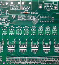
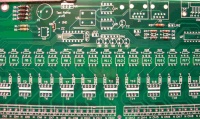
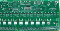
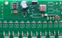
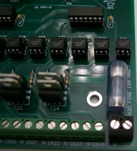
| * '''8''' - Install 25 680 ohm resistors R6, R10 thru R33 (PN# 299-680-RC). Make sure that the resistors have a value of 680 ohms (blue/grey/brown/gold stripes). These resistors have no polarity to worry about. | | * '''9''' - Install 25 680 ohm resistors R6, R10 thru R33 (PN# 299-680-RC). Make sure that the resistors have a value of 680 ohms (blue/grey/brown/gold stripes). These resistors have no polarity to worry about. |
| || [[Image:Wiki - Renard SS24 Assembly Step09.jpg | 200px]] | | || [[Image:Wiki - Renard SS24 Assembly Step09.jpg | 200px]] |
| |- | | |- |
| | | | | |
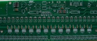
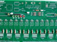
| * '''9''' - Install 24 180 ohm resistors R34 thru R57 (PN# 291-180-RC). Make sure that the resistors have a value of 180 ohms (brown/grey/brown/gold stripes). These resistors have no polarity to worry about. | | * '''10''' - Install 24 180 ohm resistors R34 thru R57 (PN# 291-180-RC). Make sure that the resistors have a value of 180 ohms (brown/grey/brown/gold stripes). These resistors have no polarity to worry about. |
| || [[Image:Wiki - Renard SS24 Assembly Step10.jpg | 200px]] | | || [[Image:Wiki - Renard SS24 Assembly Step10.jpg | 200px]] |
| |- | | |- |
| | | | | |
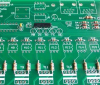
| * '''10''' - Install three 0.1uF capacitors C3, C4 & C5 (PN# 80-C322C104K5R). These capacitors have no polarity to worry about. | | * '''11''' - Install three 0.1uF capacitors C3, C4 & C5 (PN# 80-C322C104K5R). These capacitors have no polarity to worry about. |
| || [[Image:Wiki - Renard SS24 Assembly Step11.jpg | 200px]] | | || [[Image:Wiki - Renard SS24 Assembly Step11.jpg | 200px]] |
| |- | | |- |
| Line 63: |
Line 63: |
| |- | | |- |
| | | | | |
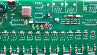
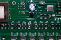
| * '''11''' - Install the 330 ohm resistor network RN1 (PN# 264-330-RC). The resistor network should have a dot on it to indicate pin 1. Insert pin 1 of the resistor network into the square solder pad (to the left). | | * '''12''' - Install the 330 ohm resistor network RN1 (PN# 264-330-RC). The resistor network should have a dot on it to indicate pin 1. Insert pin 1 of the resistor network into the square solder pad (to the left). |
| || [[Image:Wiki - Renard SS24 Assembly Step12.jpg | 200px]] | | || [[Image:Wiki - Renard SS24 Assembly Step12.jpg | 200px]] |
| |- | | |- |
| | | | | |
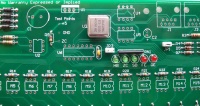
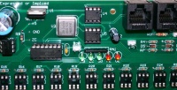
| * '''12''' - Install four green LEDs PWR (D7), HB, ZC & SD (PN# 604-WP7104GT). The LEDs are polarized and must be installed correctly. The short lead is the cathode and must be placed in the square solder pad. | | * '''13a''' - Install four green LEDs PWR (D7), HB, ZC & SD (PN# 604-WP7104GT). The LEDs are polarized and must be installed correctly. The short lead is the cathode and must be placed in the square solder pad. |
| |- | | |- |
| | | | | |
| * '''13''' - Install two red LEDs FE & OE (PN# 604-WP7104IT). The LEDs are polarized and must be installed correctly. The short lead is the cathode and must be placed in the square solder pad. | | * '''13b''' - Install two red LEDs FE & OE (PN# 604-WP7104IT). The LEDs are polarized and must be installed correctly. The short lead is the cathode and must be placed in the square solder pad. |
| || [[Image:Wiki - Renard SS24 Assembly Step13.jpg | 200px]] | | || [[Image:Wiki - Renard SS24 Assembly Step13.jpg | 200px]] |
| |- | | |- |
Board Assembly
- The following sequence of steps is by no means the only way to assemble the Renard SS24. It is simply a suggested order of events to achieve the desired goal.
- NOTE: The part numbers referenced in the following instructions are those taken from the Renard SS24 BOM.
|
|
|
- 1 - Start by checking the PCB over for any obvious production faults. Check for traces that end abruptly or have cracks/breaks in them. Also check that all holes are clear.
|
|
- 2 - Install four diodes D1 thru D4 (PN# 625-1N5817-E3). The diodes will have a silver/grey stripe on a black body. Make sure that this stripe lines up with the stripe on the PCB silk screen (to the left).
|
|
- 3 - Install two 750 ohm resistors R1 & R2 (PN# 291-750-RC). Make sure that the resistors have a value of 750 ohms (violet/green/brown/gold stripes). These resistors have no polarity to worry about.
|
|
- 4 - Install the 120 ohm resistor R3 (PN# 291-120-RC). Make sure that the resistor has a value of 120 ohms (brown/red/brown/gold stripes). This resistor have no polarity to worry about.
|
|
- 5 - Install two 1K ohm resistors R4, R7 (PN# 299-1K-RC). Make sure that the resistors have a value of 1K ohm (brown/black/red/gold stripes). These resistors have no polarity to worry about.
|
|
- 6 - Install three 27K ohm resistors R5, R8, R9 (PN# 299-27K-RC). Make sure that the resistors have a value of 27K ohms (red/violet/orange/gold stripes). These resistors have no polarity to worry about.
|
|
- 7 - Install zener diode D5 (PN# 78-1N5229B). The diode must be installed correctly. The diode should have a black stripe on the orange/red body. Make sure that this stripe lines up with the stripe on the PCB silkscreen (to the left).
|
|
- 8 - Install zener diode D6 (PN# 78-1N5239B). The diode must be installed correctly. The diode should have a black stripe on the orange/red body. Make sure that this stripe lines up with the stripe on the PCB silkscreen (to the right).
|
|
- 9 - Install 25 680 ohm resistors R6, R10 thru R33 (PN# 299-680-RC). Make sure that the resistors have a value of 680 ohms (blue/grey/brown/gold stripes). These resistors have no polarity to worry about.
|
|
- 10 - Install 24 180 ohm resistors R34 thru R57 (PN# 291-180-RC). Make sure that the resistors have a value of 180 ohms (brown/grey/brown/gold stripes). These resistors have no polarity to worry about.
|
|
- 11 - Install three 0.1uF capacitors C3, C4 & C5 (PN# 80-C322C104K5R). These capacitors have no polarity to worry about.
|
|
INSTALLATION NOTE:
The following resistor network is a "bussed" type resistor network. This means that the five resistor components (pins 2-6) are all connected in a common buss to pin 1. Installing the resistor network backwards will cause a multitude of malfunctions. So please take the time to make sure it is installed correctly.
|
- 12 - Install the 330 ohm resistor network RN1 (PN# 264-330-RC). The resistor network should have a dot on it to indicate pin 1. Insert pin 1 of the resistor network into the square solder pad (to the left).
|
|
- 13a - Install four green LEDs PWR (D7), HB, ZC & SD (PN# 604-WP7104GT). The LEDs are polarized and must be installed correctly. The short lead is the cathode and must be placed in the square solder pad.
|
- 13b - Install two red LEDs FE & OE (PN# 604-WP7104IT). The LEDs are polarized and must be installed correctly. The short lead is the cathode and must be placed in the square solder pad.
|
|
- 14 - Install three 2-pin vertical headers JP1, JP2 & JP3 (PN# 538-22-03-2021). These headers have no polarity to worry about.
|
|
- 15 - Install the clock oscillator U3 (PN# 520-TCH1843-X). The oscillator must be installed in the correct orientation. The oscillator has three rounded corners and one squared corner, make sure that the squared corner is positioned to match the PCB silkscreen (upper left corner).
|
|
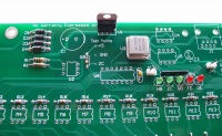
- 16 - Install the voltage regulator U1 (PN# 511-LF50CV). The voltage regulator must be installed correctly. The voltage regulators tab/heat sink must be aligned with wider line of the PCB silkscreen outline (facing towards the PCB top edge).
|
|
- 17 - Install the 2200uF capacitor C1 (PN# 647-UVR1C222MHD1TO). This capacitor is polarized and must be installed correctly. The capacitor should have a black stripe on the body to indicate which lead is negative. The positive lead of the capacitor will be the longer lead. Make sure that the positive lead is placed in the square solder pad.
|
|
- 18 - Install the 47uF capacitor C2 (PN# 647-UVR1C470MDD1TD). This capacitor is polarized and must be installed correctly. The capacitor should have a silver/grey stripe on the body to indicate which lead is negative. The positive lead of the capacitor will be the longer lead. Make sure that the positive lead is placed in the square solder pad.
|
|
- 19 - Install four fuse clips (PN# 534-3517) Note: they are directional for proper fit of the fuse. A helpful installation tip here would be to put a fuse in the clips when you position them in their mounting holes. This will help keep them correctly aligned so that the fuse will fit properly.
|
|
INSTALLATION NOTE:
Pin 1 of the following IC sockets must be aligned with the square solder pad. Another way to verify that you installed them correctly is to make sure that the notch on the socket is aligned with the notch on the PCB silkscreen outline.
|
- 20 - Install two 8-pin IC sockets for U4 & U5 (PN# 571-1-390261-2).
|
|
- 21 - Install three 14-pin IC sockets for U6, U7 & U8 (PN# 571-1-390261-3).
|
|
- 22 - Install 25 6-pin IC sockets for U2, M1 thru M24 (PN# 571-1-390261-1).
|
|
- 23 - Install 24 triacs T1 thru T24 (PN# 511-BTA04-700T). The triacs must be installed correctly. The triac tab/heat sink must be aligned with wider line of the PCB silkscreen outline. The tab/heat sink of the odd numbered triacs will facing the even numbered triacs and vice versa.
|
|
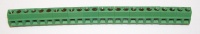
- 24 - Install 24 terminal blocks for Ch1 thru Ch24 (PN# 571-2828372). These terminal blocks have a small interlocking tab that allows the terminals to be "stacked" together to create a larger terminal block. It is easier to go ahead and "stack" twelve terminal blocks together first and then mount them on the PCB.
|
|
- 25 - Install two terminal blocks for 120V input (PN# 571-7969492).
|
|
- 26 - Install the transformer TF1 (PN# 838-3FS-312).
|
|
- 27 - Install two RJ45 modular jacks J1 & J2 (PN# 571-5556416-1). Due to minor variations in manufacturing, some RJ45 jacks are a tighter fit than others. Care should be taken to ensure that the pins are aligned first before applying too much pressure to seat the locking lugs through the board.
|
|
- 28 - Install the DE9 connector JDP1 (PN# 152-3409).
|
|
If you are unsure about your ability to build this board, then you should go to The Beginner's Setup Guide at this point. The Beginner's Setup Guide will walk you thru some initial tests to make sure that everything is working correctly before inserting the IC chips.
|
INSTALLATION NOTE:
Pin 1 of each IC must be aligned with pin 1 of the corresponding socket. This can be verified by noting that the notch on the IC is aligned with the notch on the socket.
|
- 29 - Install the H11AA1 optocoupler U2 (PN# 782-H11AA1).
|
|
- 30 - Install three PIC microcontrollers U6, U7 & U8 (PN# 579-PIC16F688-I/P). The PICs need to be programmed with the appropriate firmware before installation. More info on programming PICs can be found here.
|
|
- 31 - Install two RS232/RS485 Interface ICs U4 & U5 (PN# 511-ST485BN).
|
|
- 32 - Install 24 optoisolators M1 thru M24 (PN# 859-MOC3023).
|
|
- 33 - Install the heat sink (PN# 532-577102B00) on voltage regulator U1. The mounting hardware and heat transfer compound are not included in the BOM since any common hardware can be used to attach the heat sink. If you don't have any heat transfer compound handy, you can use PN# 532-249. In the picture the heat sink is attached using a #8 x 3/8" metal screw found at home depot.
|
|
- 34 - Install two fuses (PN# 504-GMA-10) and two fuse covers (PN# 534-3527C).
|
|
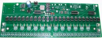
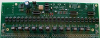
Completed Renard SS24
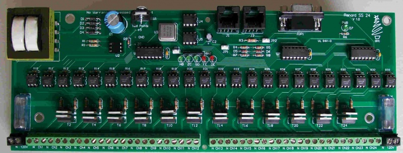 Congratulations! You have finished building your Renard SS24!
Triac Heat Sink
- A simple heat sink can be fabricated from .5"x.5"x.060" (1/16”) angle aluminum available at your local home improvement store. You can use a larger size angle if desired, but you have to keep with the 1/16" thickness. A template for the hole pattern can be found here. The triac listed in the BOM has an isolated tab, so no isolators are needed.
- A small amount of heat transfer compound should be applied between the heat sink and the tab of the triacs. You can use the same compounds that are used on computer CPU chips and their heat sinks. If you don't have any available locally, you can always use something like Mouser PN# 532-249.
Parts Listing (BOM)
IMPORTANT BOM INFORMATION:
Mouser part numbers are listed (unless otherwise noted) as a means of simplifying the listing. Mouser is not the only place to get these parts, they are used as the reference since they tend to have all the parts needed to complete the project. However, the parts can be procured from any electronics parts source that you prefer.
In the event that any of the following parts are not in stock at Mouser when you decide to order them, you can check the Part Substitutions wiki page and see if there any suggestions for alternative parts.
|
|
|
|
|
PART NUMBER
(Mouser PN# unless noted) |
QTY |
REF |
NOMENCLATURE
|
| 511-LF50CV |
1 |
U1
|
5 VDC Voltage Regulator
|
| 532-577102B00 |
1 |
|
Heatsink for Voltage Regulator
|
| 782-H11AA1 |
1 |
U2
|
Optocoupler, Bi-Directional Input
|
| 520-TCH1843-X |
1 |
U3
|
Crystal Clock Oscillator, 18.432 MHz
|
| 511-ST485BN |
2 |
U4, U5
|
Differential Bus Transceivers
|
| 571-1-390261-2 |
2 |
|
IC Socket, 8 pin (for U4 & U5)
|
| 579-PIC16F688-I/P |
3 |
U6-U8
|
PIC Microcontroller
|
| 571-1-390261-3 |
3 |
|
IC Socket, 14 pin (for U6-U8)
|
| 859-MOC3023 |
24 |
M1-M24
|
Optoisolator, Triac Driver
|
| 571-1-390261-1 |
25 |
|
IC Socket, 6 pin (for U2, M1-M24)
|
| 511-BTA04-700T |
24 |
T1-T24
|
Triac, 4A 700V
|
| 291-750-RC |
2 |
R1, R2
|
Resistor, Carbon Film 750 ohms 1/4W 5%
|
| 291-120-RC |
1 |
R3
|
Resistor, Carbon Film 120 ohms 1/4W 5%
|
| 299-1K-RC |
2 |
R4, R7
|
Resistor, Carbon Film 1K ohms 1/8W 5%
|
| 299-27K-RC |
3 |
R5, R8, R9
|
Resistor, Carbon Film 27K ohms 1/8W 5%
|
| 299-680-RC |
25 |
R6, R10-R33
|
Resistor, Carbon Film 680 ohms 1/8W 5%
|
| 291-180-RC |
24 |
R34-R57
|
Resistor, Carbon Film 180 ohms 1/4W 5%
|
| 264-330-RC |
1 |
RN1
|
Resistor Network, 6 pin, 330ohms 2%
|
| 625-1N5817-E3 |
4 |
D1-D4
|
Diode
|
| 78-1N5239B |
1 |
D6
|
Diode, Zener 9.1V .5W
|
| 78-1N5229B |
1 |
D5
|
Diode, Zener 4.3V .5W
|
| 604-WP7104IT |
2 |
FE, OE
|
LED, 3mm Red
|
| 604-WP7104GT |
4 |
PWR, HB, ZC, SD
|
LED, 3mm Green
|
| 647-UVR1C222MHD1TO |
1 |
C1
|
Radial Electrolytic Capacitor 16V 2200uF 20%
|
| 647-UVR1C470MDD1TD |
1 |
C2
|
Radial Electrolytic Capacitor 16V 47uF 20%
|
| 80-C322C104K5R |
3 |
C3-C5
|
Capacitor, Radial Ceramic 50V 0.1uF
|
| 571-2828372 |
24 |
Channel Terminals
|
Terminal Block, 2 Pos 5.08 mm
|
| 571-7969492 |
2 |
Power Terminals
|
Terminal Block, 2 Pos 5.08 mm
|
| 152-3409 |
1 |
JDP1
|
D-Sub Connectors, Right Angle DE9
|
| 571-5556416-1 |
2 |
J1, J2
|
Jack, Modular RJ45 PCB Mount Top Entry
|
| 538-22-03-2021 |
3 |
JP1-JP3
|
Header, 2 Pin
|
| 151-8000 |
3 |
|
Shunt
|
| 504-GMA-10 |
2 |
F1, F2
|
Fuse, Fast Acting 10A
|
| 534-3517 |
4 |
|
Holder, Fuse Clip PCB mount 5mm
|
| 534-3527C |
2 |
|
Cover, Fuse
|
| 838-3FS-312 |
1 |
TF1
|
Power Transformers 12.6VCT@.2A 6.3V@.4A Single Primary
|
Below is the same parts list as above but it is formatted for direct importing into the Mouser BOM feature. Just copy and paste the list as is.
511-LF50CV|1
532-577102B00|1
782-H11AA1|1
520-TCH1843-X|1
511-ST485BN|2
571-1-390261-2|2
579-PIC16F688-I/P|3
571-1-390261-3|3
859-MOC3023|24
571-1-390261-1|25
511-BTA04-700T|24
291-750-RC|2
291-120-RC|1
299-1K-RC|2
299-27K-RC|3
299-680-RC|25
291-180-RC|24
264-330-RC|1
625-1N5817-E3|4
78-1N5239B|1
78-1N5229B|1
604-WP7104IT|2
604-WP7104GT|4
647-UVR1C222MHD1TO|1
647-UVR1C470MDD1TD|1
80-C322C104K5R|3
571-2828372|24
571-7969492|2
152-3409|1
571-5556416-1|2
538-22-03-2021|3
151-8000|3
504-GMA-10|2
534-3517|4
534-3527C|2
838-3FS-312|1
Related Links
- The Renard SS24 Controller Board
- Beginners Setup Guide The Renard SS24
- Troubleshooting Guide The Renard SS24
- Board Availability Information
- Renard Main Page
- Renard Firmware
- Part Substitutions
- VIXEN
- Glossary of DIYC Terms
- Electronic Symbols


