Assembly Instructions The Renard SS8: Difference between revisions
No edit summary |
|||
| Line 64: | Line 64: | ||
*'''12''' - Install the 330 ohm resistor network RN1 (PN# 264-330-RC). The resistor network should have a dot on it to indicate pin 1. Insert pin 1 of the resistor network into the square solder pad (to the left). | *'''12''' - Install the 330 ohm resistor network RN1 (PN# 264-330-RC). The resistor network should have a dot on it to indicate pin 1. Insert pin 1 of the resistor network into the square solder pad (to the left). | ||
*'''13a''' - Install four green LEDs PWR, HB, ZC & SD (PN# 604- | *'''13a''' - Install four green LEDs PWR, HB, ZC & SD (PN# 604-WP710A10GT). The LEDs are polarized and must be installed correctly. The short lead is the cathode and must be placed in the square solder pad. | ||
*'''13b''' - Install two red LEDs FE & OE (PN# 604-WP7104IT). The LEDs are polarized and must be installed correctly. The short lead is the cathode and must be placed in the square solder pad. | *'''13b''' - Install two red LEDs FE & OE (PN# 604-WP7104IT). The LEDs are polarized and must be installed correctly. The short lead is the cathode and must be placed in the square solder pad. | ||
| Line 75: | Line 75: | ||
|- | |- | ||
| | | | ||
*'''15''' - Install the clock oscillator U3 (PN# | *'''15''' - Install the clock oscillator U3 (PN# 815-ACH-18.432-EK). The oscillator must be installed in the correct orientation. The oscillator has three rounded corners and one squared corner, make sure that the squared corner is positioned to match the PCB silkscreen (upper left corner). | ||
|| [[Image:Wiki - Renard SS8 Assemble Step14.jpg | 200px]] | || [[Image:Wiki - Renard SS8 Assemble Step14.jpg | 200px]] | ||
|- | |- | ||
| Line 83: | Line 83: | ||
|- | |- | ||
| | | | ||
*'''17''' - Install the 2200uF capacitor C1 (PN# | *'''17''' - Install the 2200uF capacitor C1 (PN# 140-REA222M1CBK1320P). This capacitor is polarized and must be installed correctly. The capacitor should have a black stripe on the body to indicate which lead is negative. The positive lead of the capacitor will be the longer lead. Make sure that the positive lead is placed in the square solder pad. | ||
|| [[Image:Wiki - Renard SS8 Assemble Step16.jpg | 200px]] | || [[Image:Wiki - Renard SS8 Assemble Step16.jpg | 200px]] | ||
|- | |- | ||
| | | | ||
*'''18''' - Install the 47uF capacitor C2 (PN# | *'''18''' - Install the 47uF capacitor C2 (PN# 140-REA470M1CBK0511P). This capacitor is polarized and must be installed correctly. The capacitor should have a silver/grey stripe on the body to indicate which lead is negative. The positive lead of the capacitor will be the longer lead. Make sure that the positive lead is placed in the square solder pad. | ||
|| [[Image:Wiki - Renard SS8 Assemble Step17.jpg | 200px]] | || [[Image:Wiki - Renard SS8 Assemble Step17.jpg | 200px]] | ||
|- | |- | ||
| Line 145: | Line 145: | ||
|- | |- | ||
| | | | ||
*'''30''' - Install the PIC microcontroller U6 (PN# 579-PIC16F688-I/P). The PIC | *'''30''' - Install the PIC microcontroller U6 (PN# 579-PIC16F688-I/P). The PIC needs to be programmed with the appropriate firmware before installation. More info on programming PICs can be found [http://www.doityourselfchristmas.com/forums/showpost.php?p=3346&postcount=1 here.] | ||
|| [[Image:Wiki - Renard SS8 Assemble Step29.jpg | 200px]] | || [[Image:Wiki - Renard SS8 Assemble Step29.jpg | 200px]] | ||
|- | |- | ||
| Line 212: | Line 212: | ||
|align="left"|Optocoupler, Bi-Directional Input | |align="left"|Optocoupler, Bi-Directional Input | ||
|- | |- | ||
| | |815-ACH-18.432-EK||1||U3 | ||
|align="left"|Crystal Clock Oscillator, 18.432 MHz | |align="left"|Crystal Clock Oscillator, 18.432 MHz | ||
|- | |- | ||
| Line 269: | Line 269: | ||
|align="left"|LED, 3mm Red | |align="left"|LED, 3mm Red | ||
|- | |- | ||
|604- | |604-WP710A10GT||4||PWR, HB, ZC, SD | ||
|align="left"|LED, 3mm Green | |align="left"|LED, 3mm Green | ||
|- | |- | ||
| | |140-REA222M1CBK1320P||1||C1 | ||
|align="left"| Radial Electrolytic Capacitor 16V 2200uF 20% | |align="left"| Radial Electrolytic Capacitor 16V 2200uF 20% | ||
|- | |- | ||
| | |140-REA470M1CBK0511P||1||C2 | ||
|align="left"| Radial Electrolytic Capacitor 16V 47uF 20% | |align="left"| Radial Electrolytic Capacitor 16V 47uF 20% | ||
|- | |- | ||
| Line 319: | Line 319: | ||
532-577102B00|1 | 532-577102B00|1 | ||
782-H11AA1|1 | 782-H11AA1|1 | ||
815-ACH-18.432-EK|1 | |||
511-ST485BN|2 | 511-ST485BN|2 | ||
571-1-390261-2|2 | 571-1-390261-2|2 | ||
| Line 338: | Line 338: | ||
78-1N5229B|1 | 78-1N5229B|1 | ||
604-WP7104IT|2 | 604-WP7104IT|2 | ||
604- | 604-WP710A10GT|4 | ||
140-REA222M1CBK1320P|1 | |||
140-REA470M1CBK0511P|1 | |||
80-C322C104K5R|1 | 80-C322C104K5R|1 | ||
571-2828372|8 | 571-2828372|8 | ||
Revision as of 22:07, 11 March 2012
Board Assembly
- The following sequence of steps is by no means the only way to assemble the Renard SS8. It is simply a suggested order of events to achieve the desired goal.
- NOTE: The part numbers referenced in the following instructions are those taken from the Renard SS8 BOM.
|

|
|

|
|

|
|

|
|

|
|

|
|

|
|

|
|

|
|

|
|

|
| |
|

|
|

|
|

|
|

|
|

|
|

|
|

|
| |
|

|
|

|
|

|
|

|
|

|
|

|
|

|
|

|
|

|
| |
| |
|

|
|

|
|

|
|

|
|

|
|

|


Triac Heat Sink
- A simple heat sink can be fabricated from .5"x.5"x.060" (1/16”) angle aluminum available at your local home improvement store. A template for the hole pattern can be found here. The triac listed in the BOM has an isolated tab, so no isolators are needed.
- Another method for making a heat sink is to use flat aluminum (1/16” thick) instead of angled. The heat sinks most commonly included in group buys are made in this fashion. The hole pattern is the same as above and the overall dimensions are shown here.
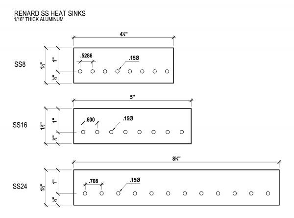
- A small amount of heat transfer compound should be applied between the heat sink and the tab of the triacs. You can use the same compounds that are used on computer CPU chips and their heat sinks. If you don't have any available locally, you can always use something like Mouser PN# 532-249.
Parts Listing (BOM)
IMPORTANT BOM INFORMATION:
Mouser part numbers are listed (unless otherwise noted) as a means of simplifying the listing. Mouser is not the only place to get these parts, they are used as the reference since they tend to have all the parts needed to complete the project. However, the parts can be procured from any electronics parts source that you prefer.
In the event that any of the following parts are not in stock at Mouser when you decide to order them, you can check the Part Substitutions wiki page and see if there any suggestions for alternative parts.
| PART NUMBER (Mouser PN# unless noted) |
QTY | REF | NOMENCLATURE |
|---|---|---|---|
| 511-LF50CVDG | 1 | U1 | 5 VDC Voltage Regulator |
| 532-577102B00 | 1 | Heatsink for Voltage Regulator | |
| 782-H11AA1 | 1 | U2 | Optocoupler, Bi-Directional Input |
| 815-ACH-18.432-EK | 1 | U3 | Crystal Clock Oscillator, 18.432 MHz |
| 511-ST485BN | 2 | U4, U5 | Differential Bus Transceivers |
| 571-1-390261-2 | 2 | IC Socket, 8 pin (for U4 & U5) | |
| 579-PIC16F688-I/P | 1 | U6 | PIC Microcontroller |
| 571-1-390261-3 | 1 | IC Socket, 14 pin (for U6) | |
| 859-MOC3023 | 8 | M1-M8 | Optoisolator, Triac Driver |
| 571-1-390261-1 | 9 | IC Socket, 6 pin (for U2, M1-M8) | |
| 511-BTA06-600CW | 8 | T1-T8 | Triac, 6A 600V |
| 291-750-RC | 2 | R1, R2 | Resistor, Carbon Film 750 ohms 1/4W 5% |
| 291-120-RC | 1 | R3 | Resistor, Carbon Film 120 ohms 1/4W 5% |
| 299-1K-RC | 2 | R4, R7 | Resistor, Carbon Film 1K ohms 1/8W 5% |
| 299-27K-RC | 3 | R5, R8, R9 | Resistor, Carbon Film 27K ohms 1/8W 5% |
| 299-680-RC | 9 | R6, R10-R17 | Resistor, Carbon Film 680 ohms 1/8W 5% |
| 291-180-RC | 8 | R18 – R25 | Resistor, Carbon Film 180 ohms 1/4W 5% |
| 264-330-RC | 1 | RN1 | Resistor Network, 6 pin, 330ohms 2% |
| 625-1N5817-E3 | 4 | D1-D4 | Diode |
| 78-1N5239B | 1 | D6 | Diode, Zener 9.1V .5W |
| 78-1N5229B | 1 | D5 | Diode, Zener 4.3V .5W |
| 604-WP7104IT | 2 | FE, OE | LED, 3mm Red |
| 604-WP710A10GT | 4 | PWR, HB, ZC, SD | LED, 3mm Green |
| 140-REA222M1CBK1320P | 1 | C1 | Radial Electrolytic Capacitor 16V 2200uF 20% |
| 140-REA470M1CBK0511P | 1 | C2 | Radial Electrolytic Capacitor 16V 47uF 20% |
| 80-C322C104K5R | 1 | C3 | Capacitor, Radial Ceramic 50V 0.1uF |
| 571-2828372 | 8 | Channel Terminals | Terminal Block, 2 Pos 5.08 mm |
| 571-7969492 | 1 | Power Terminal | Terminal Block, 2 Pos 5.08 mm |
| 152-3409 | 1 | JDP1 | D-Sub Connectors, Right Angle DE9 |
| 571-5556416-1 | 2 | J1, J2 | Jack, Modular RJ45 PCB Mount Top Entry |
| 538-22-03-2021 | 3 | JP1-JP3 | Header, 2 Pin |
| 151-8000 | 3 | Shunt | |
| 504-GMA-10 | 1 | F1 | Fuse, Fast Acting 10A |
| 534-3517 | 2 | Holder, Fuse Clip PCB mount 5mm | |
| 534-3527C | 1 | Cover, Fuse | |
| 838-3FS-312 | 1 | TF1 | Power Transformers 12.6VCT@.2A 6.3V@.4A Single Primary |
Below is the same parts list as above but it is formatted for direct importing into the Mouser BOM feature. Just copy and paste the list as is.
511-LF50CVDG|1
532-577102B00|1
782-H11AA1|1
815-ACH-18.432-EK|1
511-ST485BN|2
571-1-390261-2|2
579-PIC16F688-I/P|1
571-1-390261-3|1
859-MOC3023|8
571-1-390261-1|9
511-BTA06-600CW|8
291-750-RC|2
291-120-RC|1
299-1K-RC|2
299-27K-RC|3
299-680-RC|9
291-180-RC|8
264-330-RC|1
625-1N5817-E3|4
78-1N5239B|1
78-1N5229B|1
604-WP7104IT|2
604-WP710A10GT|4
140-REA222M1CBK1320P|1
140-REA470M1CBK0511P|1
80-C322C104K5R|1
571-2828372|8
571-7969492|1
152-3409|1
571-5556416-1|2
538-22-03-2021|3
151-8000|3
504-GMA-10|1
534-3517|2
534-3527C|1
838-3FS-312|1