Power Pops Fanout - 1 Input with 4 Outputs: Difference between revisions
Ukewarrior (talk | contribs) |
Ukewarrior (talk | contribs) (→Fuses) |
||
| Line 57: | Line 57: | ||
== Fuses == | == Fuses == | ||
[[Image:5_amp_fuse.jpg|right|small]] | |||
There is no onboard fuse for the ESPixel Pops. | There is no onboard fuse for the ESPixel Pops. | ||
Revision as of 01:58, 30 August 2017

This page is under construction
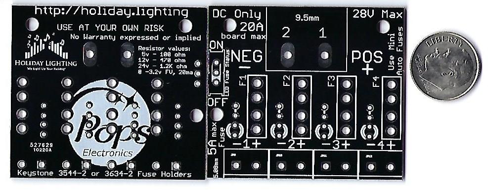
The Power Pops Fanout 1 to 4 version is a simple DC power splitter.
This board is designed to take one input DC power feed and split it into 4 outputs.
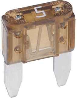
Each output on the board has an mini-automobile style fuse that is rated up to 5 amps.
Additionally, each output has a LED status indicator to show if power is flowing to that specific output; therefore showing that power is present and that the fuse is good.
There is a switch on the board that activates the function of all the status LEDs thereby allowing the user to turn off the LEDs unless needed. This switch does NOT turn off the power feed. It has no affect on the flow of power except to the LED indicators.
General Features

The Power Pops Fanout board has these main features
1. Supports the splitting of up to 20 amps of DC power into 4 individual power outlets of up to 5 amps each.
2. Is a DIY board using all through hole components for easy DIY soldering.
3. Was designed to support up to 20 amps of DC power at a maximum of 28 Volts.
4. Input & output power can be soldered directly to the board or mounted via 9.3mm(input) and 5mm(outputs) terminal blocks.
5. Each power output is individually fused with a status LED indicating the state of power and the fuse.
The board is professionally manufactured with 1oz copper and the holes are through plated. This makes for easy and more error free soldering.
The Schematic can be downloaded by clicking on this link:
Media:ESPixel_PopsSchematic.pdf
.
Order some boards
You can order your own boards from Holiday Lighting. They are stocking both bare PCBs and full Kits.
You can find them at: www.holiday.lighting.com
Fuses

There is no onboard fuse for the ESPixel Pops.
Since there is no onboard fuse, if a power overload should occur, the ESP-01 or the ESPixel Pops board may be damaged. You can add an inline fuse if desired with the input power feed.
Disclaimers
USE the Power Pops Fanout board at Your Own Risk !
The Power Pops Fanout board has NO warranty expressed or implied
BOM - Bill of Materials
The BOM contains these generically described parts:
- One ESP8266-01, this is not so much a part, but a complete subassembly.
- One diode. This must be: 1N4148
- One female socket header, 2 rows of pins, 4 pins in each row. This functions as the socket where you plug the ESP8266 module into
- One six pin header. Readily available 2.54mm (.1") pitch. (distance between the pins)
- One tactile switch. 6mm x 6mm. Also readily available. These often have choices as to the height of the push button.
- Two 1/8W or 1/4W carbon film or metal film resistors. 330 Ohms.
- One polarized Electrolytic capacitor. Any value from 10uF to 220uF will do. 10V or above. Pay special attention to the diameter and spacing of the leads. The diameter can be no more than 5mm and the leads should be spaced at 2mm.
- One MLCC monolithic capacitor. 2.54mm lead spacing. 0.1uF, any voltage over 24V. (Usually these are 50V rated) These are typically the 'yellow blob' style capacitors, verses the ones that are shaped like a flat disk. These do NOT have a + & - indication, unlike the electrolitic capacitor noted above.
- One 3.3v voltage regulator. This must be: LD1117V33, which has a TO-220 style package.
- One 5.0v voltage regulator. This part is optional and should only be installed if you are planning to drive 12v pixels.
- One Mosfet. This must be: 2N7000, which has a T0-92-3 style package
- A five pin screw terminal header. 5 positions total. This connection should have 3.81 spacing of the mounting pins.
Construction Information

The ESPixel Pops is a pretty easy build. The real trick is deciding how you plan to power your pixels as that will affect what you do with the board wiring.
Wiring The Power Pops Fanout board
Along the bottom of the board are 5 connection points. (as viewed from the top...) The two on the left are for input power. The three on the right are for pixel connection.
You can either solder on a terminal block or directly solder your wires to the board, or do a mix ! The Terminal block has 3.81mm hole spacing. (The more common 5mm terminal blocks would have made the board too wide)