GRINCH Controller Assembly Instructions: Difference between revisions
No edit summary |
|||
| Line 1: | Line 1: | ||
== | ==Board Assembly== | ||
Assembling the GRINCH should be fairly easy for most hobbyists. The following sequence of steps is by no means the only way to do this. It is simply a suggested order of events to achieve the desired goal. | |||
<br> | |||
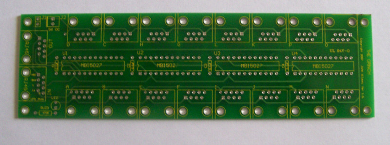
*Start by checking the PCB over for any production faults. Ensure that none of the tracks are shorted or open and that all holes are clear. | |||
[[Image:Grinch Assy Step 1.jpg]] | |||
<br> | |||
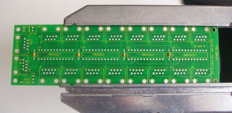
*Install the four 0.1uF capacitors (PN# 581-SA105E104Z). These capacitors have no polarity to worry about. | |||
[[Image:Grinch Assy Step 2.jpg]] | |||
<br> | |||
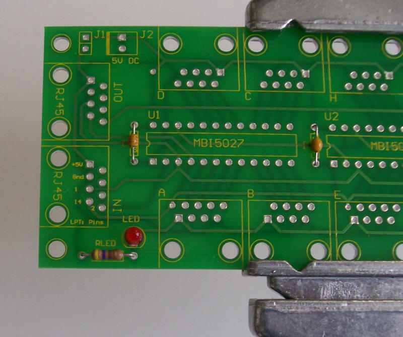
*Install the power LED (PN# 604-WP7104GC). The LED must be oriented correctly, if your LED has a flat side then match that to the overlay on the PCB. If not, then the shorter lead of the LED is the cathode and will go in the square solder pad. | |||
*Install the power LED resistor (PN# 660-CF1/4C471J). Make sure that the resistor has a value of 470ohms (yellow/violet/brown/gold stripes). The resistor has no polarity to worry about. | |||
[[Image:Grinch Assy Step 3.jpg]] | |||
The | <br> | ||
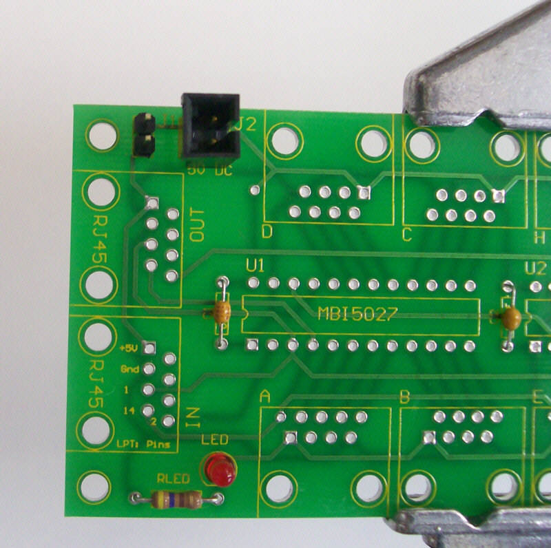
*Install the power connector at J2 (PN# 538-70543-0001). The square pad signifies the +5 VDC connection. | |||
*Install the 2 pin vertical header at J1 (PN# 538-22-03-2021). | |||
[[Image:Grinch Assy Step 4.jpg]] | |||
<br> | |||
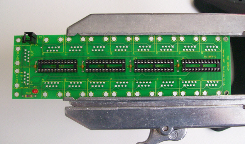
*Install the four 24 pin IC sockets (PN# 571-3902618). The sockets must be all aligned in the same direction with pin 1 of each socket aligned with the square solder pad. Another way to verify that you installed them correctly is that the notch on the top of each socket will be toward the RJ45 IN/OUT connections. | |||
[[Image:Grinch Assy Step 5.jpg]] | |||
== | <br> | ||
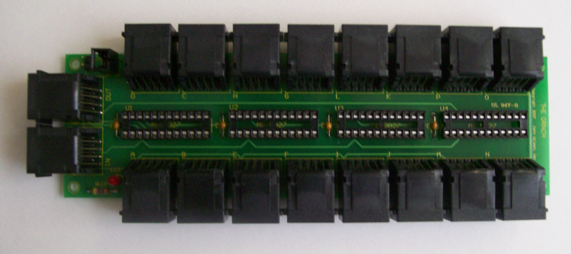
*Install the 18 RJ45 jack sockets (PN# 571-5202514). Due to minor variations in manufacturing, some RJ45 sockets are a tighter fit than others. Care should be taken to ensure that the pins are aligned first before applying too much pressure to seat the locking lugs through the board. | |||
[[Image:Grinch Assy Step 6.jpg]] | |||
<br> | |||
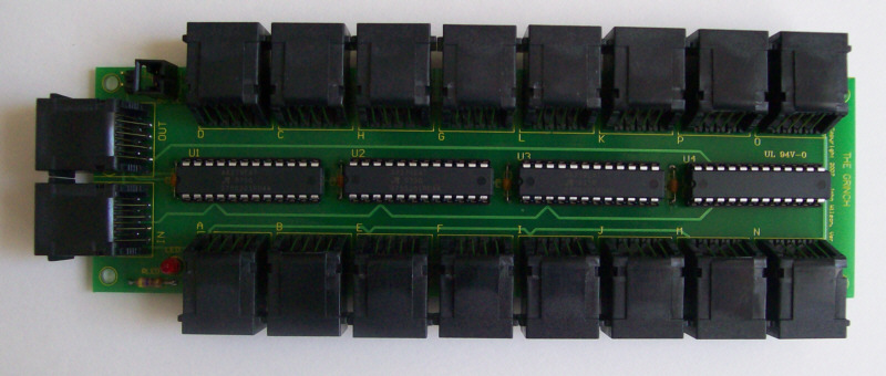
*Install the ICs into the IC sockets. Ensure that pin 1 of the IC is aligned with pin 1 of the socket. Can be verified by noting that the notch on the IC is aligned with the notch on the socket. | |||
[[Image:Grinch Assy Step 7.jpg]] | |||
<blockquote>'''CONGATULATIONS!''' You have finished your GRINCH controller board.</blockquote> | |||
==Parts Listing== | |||
| Line 59: | Line 80: | ||
571-3902618 4 | 571-3902618 4 | ||
The PCB is available from [http://www. | The PCB is available from [http://www.doityourselfchristmas.com/forums/member.php?u=11 wjohn] on the Forum. | ||
The main wiki page for [[The GRINCH Controller]] | |||
Revision as of 01:53, 15 February 2008
Board Assembly
Assembling the GRINCH should be fairly easy for most hobbyists. The following sequence of steps is by no means the only way to do this. It is simply a suggested order of events to achieve the desired goal.
- Start by checking the PCB over for any production faults. Ensure that none of the tracks are shorted or open and that all holes are clear.
- Install the four 0.1uF capacitors (PN# 581-SA105E104Z). These capacitors have no polarity to worry about.
- Install the power LED (PN# 604-WP7104GC). The LED must be oriented correctly, if your LED has a flat side then match that to the overlay on the PCB. If not, then the shorter lead of the LED is the cathode and will go in the square solder pad.
- Install the power LED resistor (PN# 660-CF1/4C471J). Make sure that the resistor has a value of 470ohms (yellow/violet/brown/gold stripes). The resistor has no polarity to worry about.
- Install the power connector at J2 (PN# 538-70543-0001). The square pad signifies the +5 VDC connection.
- Install the 2 pin vertical header at J1 (PN# 538-22-03-2021).
- Install the four 24 pin IC sockets (PN# 571-3902618). The sockets must be all aligned in the same direction with pin 1 of each socket aligned with the square solder pad. Another way to verify that you installed them correctly is that the notch on the top of each socket will be toward the RJ45 IN/OUT connections.
- Install the 18 RJ45 jack sockets (PN# 571-5202514). Due to minor variations in manufacturing, some RJ45 sockets are a tighter fit than others. Care should be taken to ensure that the pins are aligned first before applying too much pressure to seat the locking lugs through the board.
- Install the ICs into the IC sockets. Ensure that pin 1 of the IC is aligned with pin 1 of the socket. Can be verified by noting that the notch on the IC is aligned with the notch on the socket.
CONGATULATIONS! You have finished your GRINCH controller board.
Parts Listing
The parts List for the GRINCH is fairly basic.
1 PC Board, Code GRINCH V1.0 (Supplied by John Wilson)
18 RJ45-8/8 right angle sockets (Mouser # 571-5202514)
1 Molex .100 KK. Vertical Header 2 Pin (Mouser # 538-22-03-2021)
1 FCI Bergcon PCB shunt (jumper) (Mouser #649-65474-002LF)
1 Molex SL connector Vertical Header 2 Pin (Mouser # 538-70543-0001)
1 Molex SL Connector Vertical Plug 2 Pin (Mouser # 538-50-57-9402)
2 Molex SL Connectors Female (Mouser # 538-16-02-0102)
4 Axial Ceramic 50V 0.1uF (Mouser # 581-sa105e104z)
1 Green LED 3 mm (Mouser # 604-wp7104gc)
1 470 Ohm 1/4 Watt Resistor (Mouser # 660-cf1/4c471j)
4 24 Pin IC Socket (Mouser # 571-3902618)
4 MBI5027-GN (From King Electronics)
Here is the list in Mouser BOM format;
 571-5202514 18
 538-22-03-2021 1
 649-65474-002LF 1
 538-70543-0001 1
 538-50-57-9402 1
 538-16-02-0102 2
 581-sa105e104z 4
 604-wp7104gc 1
 660-cf1/4c471j 1
 571-3902618 4
The PCB is available from wjohn on the Forum.
The main wiki page for The GRINCH Controller
