FM02 Gallery: Difference between revisions
Jump to navigation
Jump to search
Ukewarrior (talk | contribs) |
Ukewarrior (talk | contribs) |
||
| Line 2: | Line 2: | ||
<gallery caption="FM02 Installations. Click on the pictures to enlarge." widths="150px" heights="150px" perrow="4"> | <gallery caption="FM02 Installations. Click on the pictures to enlarge." widths="150px" heights="150px" perrow="4"> | ||
Image:FM02_OregonLights.jpg|The water tight case with mounting tabs is from Mouser P/N 563-NBF-32006. The plastic is thick but pliable, very easy to drill and work with. The power is via a wall wart, goes in through a strain relief and into toggle switch and power indicating LED I got at Radio Shack. The power then goes into a LM317 regulator I bought in the DIYC group buy. For additional power filtering I added two 2200 uF capacitors to the output of the LM317 and routed it into the transmitter. The audio input is provided off a headphone jack from the computer line out. A stereo jack is mounted in the case and routed into the transmitter so a standard stereo cable can be used off the computer. I put a snap on ferrite bead (mouser P/N 810-ZCAT1730-0730A $1.20) onto the audio cable .The transmitter board in the cover is attached using screws through the case lid and nylon spacers I got from Ace Hardware. The case is thick enough I had to put a relief in for some components to make the frequency display sit flush with the outside of the case. The boards on the inside of the case are mounted to a thin plexiglass panel I made from a larger piece I got from Lowes. I just scored it and snapped to fit. It mounts with two screws into the case body. The boards are attached to the plexiglass plate using screws and nylon spacers and some larger nuts. | Image:FM02_OregonLights.jpg|By OregonLights. The water tight case with mounting tabs is from Mouser P/N 563-NBF-32006. The plastic is thick but pliable, very easy to drill and work with. The power is via a wall wart, goes in through a strain relief and into toggle switch and power indicating LED I got at Radio Shack. The power then goes into a LM317 regulator I bought in the DIYC group buy. For additional power filtering I added two 2200 uF capacitors to the output of the LM317 and routed it into the transmitter. The audio input is provided off a headphone jack from the computer line out. A stereo jack is mounted in the case and routed into the transmitter so a standard stereo cable can be used off the computer. I put a snap on ferrite bead (mouser P/N 810-ZCAT1730-0730A $1.20) onto the audio cable .The transmitter board in the cover is attached using screws through the case lid and nylon spacers I got from Ace Hardware. The case is thick enough I had to put a relief in for some components to make the frequency display sit flush with the outside of the case. The boards on the inside of the case are mounted to a thin plexiglass panel I made from a larger piece I got from Lowes. I just scored it and snapped to fit. It mounts with two screws into the case body. The boards are attached to the plexiglass plate using screws and nylon spacers and some larger nuts. | ||
Image:FM02_OregonLights_2.jpg|Mounted view of the FM02 to the left. | Image:FM02_OregonLights_2.jpg|By OregonLights. Mounted view of the FM02 to the left. | ||
Image:Fm02_underdog.jpg|My take on a few similar ideas. It's shown here with the testing whip antenna, so far Its working quite well, small audible buzz , but for testing purposes with the antenna, I'm sure it's fixable. (Actually now that I've messed with it, I've figured out that its the output signal that is causing the buzz. The front output is the far worse than the output in the back...and when I switch to an MP3 player and its pure, VERY clean, even with the small antenna! Maybe this is an excuse to get a standalone sound card! | Image:Fm02_underdog.jpg|By Underdog. My take on a few similar ideas. It's shown here with the testing whip antenna, so far Its working quite well, small audible buzz , but for testing purposes with the antenna, I'm sure it's fixable. (Actually now that I've messed with it, I've figured out that its the output signal that is causing the buzz. The front output is the far worse than the output in the back...and when I switch to an MP3 player and its pure, VERY clean, even with the small antenna! Maybe this is an excuse to get a standalone sound card! | ||
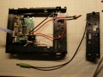
Like others, I've taken an old CD player that was no longer functional and gutted it, desoldered the main connection bar and then pulled out all but 2 pins, the ground and the +12V. That makes it easier to not have to cut into the PSU harness and maintain the stock plug! I added a switch and a line input (Neither labeled yet). I also added a 24V 2200uf cap to the input of computer power supply, as recommended by Dirk. The last real mod was I had the front panel on risers off the front, but after clicking around on the front buttons some I felt like it was bending the board, so the "KISS" method best solution was to remove the risers, take an old mouse pad, cut out a piece of the neoprene-like rubber and the place it behind the board to give more support. Much better, It feels much more secure. | Like others, I've taken an old CD player that was no longer functional and gutted it, desoldered the main connection bar and then pulled out all but 2 pins, the ground and the +12V. That makes it easier to not have to cut into the PSU harness and maintain the stock plug! I added a switch and a line input (Neither labeled yet). I also added a 24V 2200uf cap to the input of computer power supply, as recommended by Dirk. The last real mod was I had the front panel on risers off the front, but after clicking around on the front buttons some I felt like it was bending the board, so the "KISS" method best solution was to remove the risers, take an old mouse pad, cut out a piece of the neoprene-like rubber and the place it behind the board to give more support. Much better, It feels much more secure. | ||
| Line 13: | Line 13: | ||
The next step will be routing the RG58 antenna to the back of the box. I've got all the SMA hardware for the antenna output and antenna. (Perhaps next weekend). Any questions, professional criticisms, recommendations, or critiques; Always welcome. Also, with all that extra space, RDS would be nice to add in...hmmm... | The next step will be routing the RG58 antenna to the back of the box. I've got all the SMA hardware for the antenna output and antenna. (Perhaps next weekend). Any questions, professional criticisms, recommendations, or critiques; Always welcome. Also, with all that extra space, RDS would be nice to add in...hmmm... | ||
Image: Fm02_underdog_2.jpg| Additional image to the left | Image: Fm02_underdog_2.jpg| By Underdog. Additional image to the left | ||
Image: Fm02_captkirk.JPG| Mounted in an Aluminum case | Image: Fm02_captkirk.JPG| By CaptKirk. Mounted in an Aluminum case | ||
</gallery> | </gallery> | ||
Revision as of 16:04, 29 December 2011
Pictures of Various FM02 Installations
- FM02 Installations. Click on the pictures to enlarge.
-
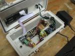 By OregonLights. The water tight case with mounting tabs is from Mouser P/N 563-NBF-32006. The plastic is thick but pliable, very easy to drill and work with. The power is via a wall wart, goes in through a strain relief and into toggle switch and power indicating LED I got at Radio Shack. The power then goes into a LM317 regulator I bought in the DIYC group buy. For additional power filtering I added two 2200 uF capacitors to the output of the LM317 and routed it into the transmitter. The audio input is provided off a headphone jack from the computer line out. A stereo jack is mounted in the case and routed into the transmitter so a standard stereo cable can be used off the computer. I put a snap on ferrite bead (mouser P/N 810-ZCAT1730-0730A $1.20) onto the audio cable .The transmitter board in the cover is attached using screws through the case lid and nylon spacers I got from Ace Hardware. The case is thick enough I had to put a relief in for some components to make the frequency display sit flush with the outside of the case. The boards on the inside of the case are mounted to a thin plexiglass panel I made from a larger piece I got from Lowes. I just scored it and snapped to fit. It mounts with two screws into the case body. The boards are attached to the plexiglass plate using screws and nylon spacers and some larger nuts.
 -
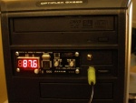
 By OregonLights. Mounted view of the FM02 to the left.
 -
 By Underdog. My take on a few similar ideas. It's shown here with the testing whip antenna, so far Its working quite well, small audible buzz , but for testing purposes with the antenna, I'm sure it's fixable. (Actually now that I've messed with it, I've figured out that its the output signal that is causing the buzz. The front output is the far worse than the output in the back...and when I switch to an MP3 player and its pure, VERY clean, even with the small antenna! Maybe this is an excuse to get a standalone sound card!
 -
 By Underdog. Additional image to the left
 -
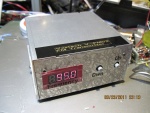 By CaptKirk. Mounted in an Aluminum case


