FM02 Gallery: Difference between revisions
Ukewarrior (talk | contribs) |
Ukewarrior (talk | contribs) |
||
| Line 2: | Line 2: | ||
<gallery caption="FM02 Installations. Click on the pictures to enlarge. Be sure to scroll down the page." widths="150px" heights="150px" perrow="4"> | <gallery caption="FM02 Installations. Click on the pictures to enlarge. Be sure to scroll down the page." widths="150px" heights="150px" perrow="4"> | ||
Image:FM02_OregonLights.jpg|By OregonLights. The water tight case with mounting tabs is from Mouser P/N 563-NBF-32006. The plastic is thick but pliable, very easy to drill and work with. The power is via a wall wart, goes in through a strain relief and into toggle switch and power indicating LED I got at Radio Shack. The power then goes into a LM317 regulator I bought in the DIYC group buy. For additional power filtering I added two 2200 uF capacitors to the output of the LM317 and routed it into the transmitter. The audio input is provided off a headphone jack from the computer line out. A stereo jack is mounted in the case and routed into the transmitter so a standard stereo cable can be used off the computer. I put a snap on ferrite bead (mouser P/N 810-ZCAT1730-0730A $1.20) onto the audio cable .The transmitter board in the cover is attached using screws through the case lid and nylon spacers I got from Ace Hardware. The case is thick enough I had to put a relief in for some components to make the frequency display sit flush with the outside of the case. The boards on the inside of the case are mounted to a thin plexiglass panel I made from a larger piece I got from Lowes. I just scored it and snapped to fit. It mounts with two screws into the case body. The boards are attached to the plexiglass plate using screws and nylon spacers and some larger nuts. | Image:FM02_OregonLights.jpg|By OregonLights. <p>The water tight case with mounting tabs is from Mouser P/N 563-NBF-32006. The plastic is thick but pliable, very easy to drill and work with. The power is via a wall wart, goes in through a strain relief and into toggle switch and power indicating LED I got at Radio Shack. The power then goes into a LM317 regulator I bought in the DIYC group buy. For additional power filtering I added two 2200 uF capacitors to the output of the LM317 and routed it into the transmitter. The audio input is provided off a headphone jack from the computer line out. A stereo jack is mounted in the case and routed into the transmitter so a standard stereo cable can be used off the computer. I put a snap on ferrite bead (mouser P/N 810-ZCAT1730-0730A $1.20) onto the audio cable .The transmitter board in the cover is attached using screws through the case lid and nylon spacers I got from Ace Hardware. The case is thick enough I had to put a relief in for some components to make the frequency display sit flush with the outside of the case. The boards on the inside of the case are mounted to a thin plexiglass panel I made from a larger piece I got from Lowes. I just scored it and snapped to fit. It mounts with two screws into the case body. The boards are attached to the plexiglass plate using screws and nylon spacers and some larger nuts. </p> | ||
Image:FM02_OregonLights_2.jpg|By OregonLights. Mounted view of the FM02 to the left. | Image:FM02_OregonLights_2.jpg|By OregonLights. Mounted view of the FM02 to the left. | ||
Revision as of 16:08, 29 December 2011
Pictures of Various FM02 Installations
- FM02 Installations. Click on the pictures to enlarge. Be sure to scroll down the page.
-
 By OregonLights.
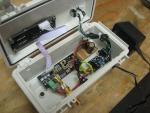
The water tight case with mounting tabs is from Mouser P/N 563-NBF-32006. The plastic is thick but pliable, very easy to drill and work with. The power is via a wall wart, goes in through a strain relief and into toggle switch and power indicating LED I got at Radio Shack. The power then goes into a LM317 regulator I bought in the DIYC group buy. For additional power filtering I added two 2200 uF capacitors to the output of the LM317 and routed it into the transmitter. The audio input is provided off a headphone jack from the computer line out. A stereo jack is mounted in the case and routed into the transmitter so a standard stereo cable can be used off the computer. I put a snap on ferrite bead (mouser P/N 810-ZCAT1730-0730A $1.20) onto the audio cable .The transmitter board in the cover is attached using screws through the case lid and nylon spacers I got from Ace Hardware. The case is thick enough I had to put a relief in for some components to make the frequency display sit flush with the outside of the case. The boards on the inside of the case are mounted to a thin plexiglass panel I made from a larger piece I got from Lowes. I just scored it and snapped to fit. It mounts with two screws into the case body. The boards are attached to the plexiglass plate using screws and nylon spacers and some larger nuts.
-
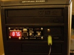
 By OregonLights. Mounted view of the FM02 to the left.
 -
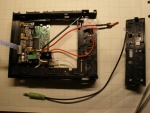
 By Underdog. My take on a few similar ideas. It's shown here with the testing whip antenna, so far Its working quite well, small audible buzz , but for testing purposes with the antenna, I'm sure it's fixable. (Actually now that I've messed with it, I've figured out that its the output signal that is causing the buzz. The front output is the far worse than the output in the back...and when I switch to an MP3 player and its pure, VERY clean, even with the small antenna! Maybe this is an excuse to get a standalone sound card!
 -
 By Underdog. Additional image to the left
 -
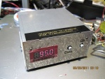 By CaptKirk. Mounted in an Aluminum case


