Renard Connection Instructions (early Renard Designs): Difference between revisions
Phil Short (talk | contribs) |
Phil Short (talk | contribs) No edit summary |
||
| Line 2: | Line 2: | ||
The Renard controllers fall into two basic categories. Some controllers have SSRs included on the controller PCB, and are connected directly to the AC power lines and to the AC load (lights, usually). Other controllers work with separate SSRs, and are not directly connected to the AC power line (except maybe to supply a zero-crossing signal). | The Renard controllers fall into two basic categories. Some controllers have SSRs included on the controller PCB, and are connected directly to the AC power lines and to the AC load (lights, usually). Other controllers work with separate SSRs, and are not directly connected to the AC power line (except maybe to supply a zero-crossing signal). | ||
'''Important note regarding Renard64''' | |||
There were some typos in the Renard64 zero-crossing section that have been corrected, please read that section carefully if you are bringing in the zero-crossing signal through J4. | |||
=== Ren-T (Transformer Board) === | === Ren-T (Transformer Board) === | ||
Revision as of 14:47, 25 September 2007
This page describes how to connect up the various Renard controllers that have been made available for others to build.
The Renard controllers fall into two basic categories. Some controllers have SSRs included on the controller PCB, and are connected directly to the AC power lines and to the AC load (lights, usually). Other controllers work with separate SSRs, and are not directly connected to the AC power line (except maybe to supply a zero-crossing signal).
Important note regarding Renard64
There were some typos in the Renard64 zero-crossing section that have been corrected, please read that section carefully if you are bringing in the zero-crossing signal through J4.
Ren-T (Transformer Board)
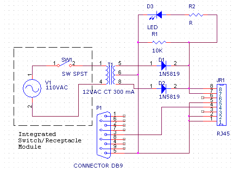
Here is the schematic of a transformer board that may be useful for bring the input (RS232), the zero-crossing signal (and low-voltage power, in some cases) to the Renard controllers. The current rating of the transformer is good for powering perhaps four Renard8 boards (assuming 75 mA each). This transformer board can be used to bring input signals and zero-crossing signals into the Renard64 board and into the Ren-C converter, although some other method must be used supply low-voltage power to the controller (the Renard64 requires 1A when the status LEDs are installed, and the Ren-C board draws power from the 595 board that it is attached to).
The various Renard boards all have several different connection options, and must be configured properly to use this transformer board. You can find the instructions for configuring the Ren-T for different applications here .
Note: the filter cap on the Renard16 board is too small to work with the transformer board at this time. That board must be powered using an externally filtered supply.
Note: the 1N5819 diodes can be replaced with 1N4001 diodes, especially if you are not using this board to provide power to the Renard controller (i.e. you are using it just for the input signal zero-crossing connections.
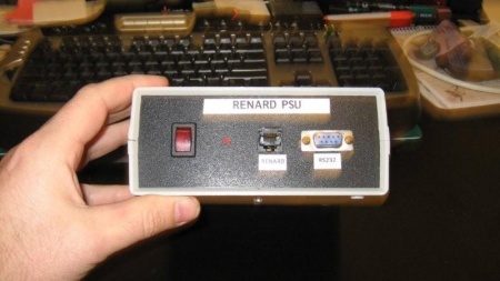
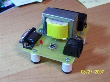
Wjohn's home made power supply, based on the circuit above.
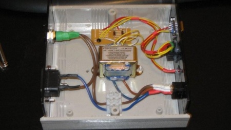
Inside wjohn's home made power supply, based on the circuit above. The case is an ABS instrument case, and the transformer is mounted using plastic hardware (insulated). The RJ45 is a PCB mount version, that has been 'hot glued' to the front panel. The wiring is kept tidy by using heat shrink tubing around the cable runs. AC is connected to the PSU via the IEC socket on the rear panel. A panel mounted fuse holder is used to keep things safe and an illuminated power switch and DC powered LED provide inidication of status of the PSU on the front panel.
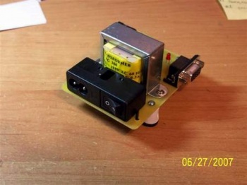
Below is a PCB based version of the power supply. This was the first version constructed by Wayne. Version 2 will include onboard RS-232 to RS-485 conversion, as well as the power supply in Version 1. The Ren-T V2.4 is now being used, and can be seen here
Controllers with Integrated SSRs
Xmus 16-Channel Controller
Frank Kostyun 24-Channel Controller
Controllers without Integrated SSRs
Renard8
Renard64
The power requirements for Renard64 depend on how the board is assembled. If the LEDs are installed on the board and the PWM firmware is used (so that the on-board status LEDS dim), the board will require about 1A at +5V. If the LEDs are omitted but the PWM firmware is used, the board will require about 0.5A (this configuration might be needed for use with LED strings). If the non-PWM firmware is used, the board will need less than 100 mA (regardless of whether the status LEDs are installed or not. These instructions (for now) assume that the first option above is chosen.
To use the Renard64 board with the transformer board described above, the Renard64 board must be assembled as follows:
1) Omit U6 (H11AA1), R1, R2 and J1
2) Install Q1 (2N3904)
3) Install R14 (10K)
4) Jumper J2-2 to J2-3
5) Omit D1
In this case, the easiest way to bring the regulated 5V power into the Renard64 board is to install a 3-pin Molex connector in place of U1 (omitting D1, as indicated above, and also omit C1), and use a PC power supply to provide 5V power (Ground to Pin 2, +5V to pin 3, leave Pin 1 open). An alternative method of bringing regulated 5V power into the board is to use pins 7,8 of the input RJ45 connector (bring the zero-crossing in through J1, J3-3, or J17, and place jumpers across D1 and across pins 1,3 of U1).
Renard-595 Converter
Connections
Serial Connections
RS232
The connection from the PC to the transformer board is via a straight thru cable.
The PC end of the cable is a Female DB-9, and the transformer board end of the cable is a Male DB-9.
There are only two wires required:
 Pin # 3  (Transmit Data)
 Pin # 5  (Gnd)
RS485
Controller Power Connections (low-voltage)
Zero-Crossing Connections
Renard64
There are several possible methods of bring the zero-crossing signal onto the board.
Method 1) Bring rectified but unfiltered DC into J3-7,8 using the transformer board. This is viewed as the easiest, safest method. In this case you need to jumper J2-2 to J2-3, and to install R9, Q1, and R14.
Method 2) Bring rectified, unfiltered DC into J3-3. This may be less convenient than method 1, but allows you to use J3-7,8 to bring regulated DC power into the board. In this case you need to jumper J2-1 to J2-2, and install R9, Q1 and R14.
Method 3) Bring AC into J1. This AC can be 110VAC (somewhat hazardous) if R1 and R2 are each 15K, 1/2W resistors (provides 50% safety margin on the power ratings of R1, R2). It can also be a lower AC voltage, such as the direct output of a 12VAC or 24VAC transformer (R1 and R2 should be proportionately lower in value). You should probably not install Q1 in any of these cases. In all of these cases U6 (the H11AA1) and R14 should be installed.
Method 4) Bring the zero-crossing signal in through J17, which goes directly to the input of the PIC chips without any intermediate protection or buffering. The reasons why you would do this and the method of doing it are left up to your imagination and skill.
