How Dimming Works
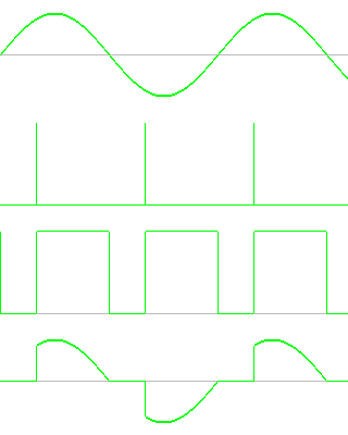
This diagram shows how dimming is implemented using the Renard system (and many of the other systems that hobbyists are using).
The top waveform is the AC powerline voltage.
The second waveform shows the timing of the SSR trigger signal (non-pwm case).
The third waveform shows the timing of the SSR trigger signal in the pwm case.
The last waveform is the voltage that appears across the load (lights).

Reference: Dimmers Dave Fansler has a nice write-up on dimming at his site, and almost all of the information there is directly applicable here.