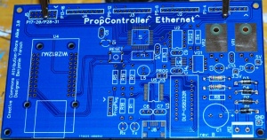
Assembly Instructions
THIS PAGE IS A WORK IN PROGRESS
This is in no way shape or form the only way to assemble a PropController.
Part Numbers referenced are taken from the Ethernet PropController BOM.
_Issue with VR1/VR2 placement to be updated_
Tips
- Start by checking the PCB for any obvious faults, missing/broken traces, holes that aren't clear, etc.
- Clean the PCB with Rubbing Alcohol (atleast 70%) or other PCB cleaner. (Not required, makes things a bit easier though).
- Get your parts together in order of assembly step, and insure you have the correct number of all needed.
Assembling the Board
Power and Zero Crossing
|
|
|
- Install four diodes (D1 - D4) P/N: 1N5817DICT-ND. The diodes have a strip (silver/grey) that must line up with the white silkscreen on the PCB.
|
|
- Install the two 750 Ohm 1/4W resistors (R 6 - R 7) P/N: 750QBK-ND. The color bands are Violet, Green, Brown, Gold. The resistors have no polarity to worry about.
|
|
- Install the three 10k Ohm 1/4W resistors (R 4, R 8, R 22) P/N: 10KQBK-ND. The color bands are (Brown, Black, Orange, Gold). The resistors have no polarity to worry about.
- Install the two 47uF capacitors (C2 - C3) P/N: 445-2905-ND. These capacitors have no polarity to worry about.
- Install the four 0.1uF capacitor (C4, C7, C9, C13) P/N: 445-2634-ND. This capacitor has no polarity to worry about.
- Install the 5V Volt Regulator (VR1) P/N: 497-1404-5-ND. The regulator gets installed with the tab attached to the board with the heat-sink sandwiched in the middle. Be careful not to torque the leads too much when bending them.
- Install the 3.3 Volt Regulator (VR2) P/N: LM2937ET-3.3-ND. The regulator gets installed with the tab attached to the board with the heat-sink sandwiched in the middle. Be careful not to torque the leads too much when bending them.
- Install the Terminal Block (J12) P/N: ED2600-ND. The terminal block gets installed with the holes facing outward.
- Install the 2200uF capacitor (C1) P/N: P5143-ND. The capacitor _does_ have a polarity. The - - - stripe on the side of the capacitor goes into the Negative lead.
- Install the Zero Crossing chip (VO1) P/N: H11AA1M-ND. The chip gets installed with the indent matching the silkscreen and the dot denoting pin one matching the silkscreen. (Note: in the picture, you will see a socket, I prefer to put sockets on most of my chips, personal preference, not required).
Test the Power
Main Board
- Install the Propeller IC (U1) P/N: P8X32A-Q44-ND. (Orientation Note)
- Install the 2K EEPROM Chip (U6) P/N: 24AA025E48-I/SN-ND (Orientation Note)
- Install the 512K EEPROM Chip (U2) P/N: 24LC512-I/P-ND (Orientation Note)
- Install the four 150 Ohm 1/4W resistors (R 1, R 5, R 18, R 19) P/N: 150QBK-ND . The color bands are Brown, Green, Brown, Gold. The resistors have no polarity to worry about.
- Install the 220 Ohm 1/4W resistor (R 3). P/N: 220QBK-ND. The color bands are Red, Red, Brown, Gold. The resistors have no polarity to worry about.
- Install the 33k Ohm 1/4W resistor (R 2). P/N: 33KQBK-ND. The color bands are Orange, Orange, Orange, Gold. The resistors have no polarity to worry about.
- Install the 5MHz Crystal (X1) P/N: XC1711-ND. There is no polarity or orientation to worry about.
- Install the 5mm Red/Green LED (L3) P/N: 754-1278-ND (Orientation Note)
- Install the Reset Switch (PB1) P/N: 450-1650-ND. (Orientation Note)
- Install the Transistor (Q1) P/N: P2N2222AGOS-ND. Make sure the body of the package lines up with the silkscreen on the PCB.
- Install the Female Headers P/N: S7078-ND for the WizNet Module. They have no orientation, but make sure they sit flush with the PCB.
- Install the four 8-Position Male Headers (J1 - J4) P/N: WM4206-ND. Be sure they sit flush with the PCB. (It is helpful to tack 1 pin down and re-adjust if necessary)
- Install the 12-Position Male Header (J5) P/N: WM8124-ND. Be sure it sits flush with the PCB. (It is helpful to tack 1 pin down and re-adjust if necessary)
- Install the 2-Position Male Header (J13) P/N: WM8072-ND. Be sure that it sits flush with the PCB. (It is helpful to tack 1 pin down and re-adjust if necessary)
USB Connection (SMT Option)
- Install the USB Mini Connector (J11) P/N: 732-2109-ND
- Install the FTDI 232 Chip (U5) P/N: 768-1007-1-ND.
- Install the 4.7uF capacitor (C6) P/N: 445-2867-ND. This capacitor has no polarity to worry about.
- Install the 0.1uF capacitor (C7) P/N: 445-2634-ND. This capacitor has no polarity to worry about.
- Install the 3mm Red LED (L1) P/N: 754-1243-ND (Orientation Note)
- Install the 3mm Green LED (L2) P/N: 754-1242-ND (Orientation Note)
USB Connection (Through Hole Option)
|
