DCSSR Version 2.4
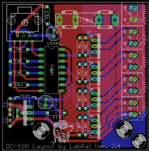
DCSSR Version 2.4 - 4 Channel DC SSR - layout by Labrat
THIS WIKI IS A WORK IN PROGRESS AND IS CURRENTLY UNDER CONSTRUCTION. PLEASE DO NOT FOLLOW THE INSTRUCTIONS UNTIL IT IS FINISHED!!!!!
Draft Written 03/15/12
Please see the standard Disclaimers
What is the DCSSR Version 2.4?
The DCSSR Version 2.4 is a 4 channel DC SSR (Solid State Relay) used to switch medium/high current DC loads such as high power LEDS, Dumb RGB Strips, DC Floodlights, solenoids, etc. The DCSSR Version 2.4 is connected to a computer thru a controller and is directly connected to your dc load and dc power supply. The DCSSR is connected to a controller such as the Ren64XC or the Ren48LSD to provide the signals necessary to turn the DCSSR on and off. It is capable of controlling DC loads from 5 - 24V. Each channel is rated for 4A and the total load for all four channels combined is 10A. The original concept design was created by DIYC user John Wilson (wjohn). This version of the layout was designed by Andrew Williams (LabRat) of Ottawa, Canada, in the spring of 2012, with the intent to make a board that would fit inside the TA-200 enclosure.
How does the DCSSR work?
The DCSSR Version 2.4 was designed to be used primarily to drive medium/high current DC loads that require a higher current then can be provided by other DC units such as the stand alone REN48LSD. The design allow 4 channels to be switched on/off or dimmed by switching the N Channel Mosfets on and off which provides a ground to the devices connected to the respective channels. It provides a common V+ across all of the channels.
The DCSSR Version 2.4 uses an Optoisolator to isolate the controller from the DC loads being switched. The input signals come from the DC controller using ordinary Cat5 cable plugged in to the controller and the DCSSR Version 2.4. The power for the DC loads is connected to the DC In terminals near the top right of the board and the 4 channel of DC loads are connected to the terminals along the right side of the board.
Revision History
The Version 2.4 is currently the most recent version of the DCSSR designed by Labrat in production.
Previous version (1.6) is detailed in the "Files Section" of the DIYC website. TA200 DCSSR Version 1.6
For wjohn DCSSR Versions 1.0-1.3 look here.
DCSSR Version 2.4 Parts
In addition to the PCB, you will need the following components:
Mouser
| Mouser BOM | ||
| Mouser PN | Description | Qty |
| 534-3517 | Fuseholders, Clips, & Hardware PC FUSE CLIP 5 MM | 2 |
| 660-CF1/4C103J | Carbon Film Resistors - Through Hole 10Kohms 5% | 4 |
| 80-C322C104Z5U | Multilayer Ceramic Capacitors (MLCC) - Leaded 50volts 0.1uF Z5U | 2 |
| 512-LM78L05ACZX | Linear Regulators - Standard TO-92 .1A Pos Volt | 1 |
| 660-CFS1/4CT52R471J | Carbon Film Resistors - Through Hole 470 OHM 5% 1/4W | 4 |
| 660-CFS1/4CT52R681J | Carbon Film Resistors - Through Hole 680 OHM 5% 1/4W | 4 |
| 782-K847PH | Transistor Output Optocouplers Phototransistor Out Quad CTR 50-600% | 1 |
| 538-39890-0302 | Fixed Terminal Blocks 5.0MM ECONOMY 2P 14-24AWG | 5 |
| 571-1-390261-4 | IC & Component Sockets 16P ECONOMY TIN | 1 |
| 512-FQPF13N06L | MOSFET 60V N-Channel QFET Logic Level | 4 |
| 571-5556416-1 | Ethernet & Telecom Connectors 8 PCB TOP ENTRY | 1 |
| 604-WP7113ID | Standard LED - Through Hole HI EFF RED DIFFUSED | 1 |
| 604-WP7113GD | Standard LED - Through Hole GREEN DIFFUSED | 1 |
| 71-CCF071K00GKE36 | Metal Film Resistors - Through Hole 1/4watt 1Kohms 2% Rated to 1/2watt | 2 |
| 504-GMA-10 | 10A Fuse | 1 |
Heatsink
The design calls for a heatsink to be attached to the MOSFETS to provide maximum power handling capability. It may be purchased at www.diyledexpress.com
Housing
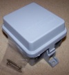
The DCSSR Version 2.4 was designed to fit in the TA-200 Demarcation Enclosure available from numerous vendors including www.wlcventures.com

Building the DCSSR Version 2.4
Assembly
The DCSSR Version 2.4 is a simple device to assemble and test. It is easiest if you build the units by inserting the various components from smallest to tallest .
- Begin by inspecting the PCBs to look for any defects such as cracks or breaks. The holes on the board should be open on both sides. Then inspect and sort out the various parts for the board.
- Install the resistors:
- four 470 ohm resistors in positions R1-R4 in the center of the board. The resistors are not polarized so they can go either way.
- four 10K ohm resistors in positions R5-R8 in the center of the board. The resistors are not polarized so they can go either way.
- four 680 ohm resistors in positions R9-R12 on the left side of the board. The resistors are not polarized so they can go either way.
- two 1K ohm resistors in positions R13-R14 on the top left and bottom left of the board. The resistors are not polarized so they can go either way.
- Install the two 0.1 uF capacitors in positions C1-C2 on the bottom left of the board. The capacitors are not polarized so they can go either way.
- Install the Install the 16 pin socket in the center of the board. Note that the notch faces the top of the board matching the silkscreen pattern on the PCB.
- Install the light emitting diodes:
- Install the Green LED in the position marked Signal near the top of the board next to the RJ45 jack. Note that the LED is polarized and long lead should go towards the bottom of the board.
- Insert the Red LED in the position marked Power near the bottom left of the board. Note that the LED is polarized and the long lead should face towards the top of the board.
- Install the 5v linear regulator on the bottom left side of the board. Note that there are two sets of three holes. If you are using the small TO-92 package regulator listed in the BOM then the 7805 will use the holes closest to the caps. Note the regulator is polarized and the flat side should face left to match the orientation on the silkscreen.
- Install the two fuse clips near the top center of the circuit board. It may be easier to put the fuse in then install them on the PCB to ensure they are installed in the correct direction and line up. Please note that fuse clips may be polarized. Examine them carefully, as they often have extra bends that should be placed on the outside end, to stop the fuse from slipping out. Be careful, the fuse holders require a fair amount of solder and heat to attach them. The FUSE should not be present when installing the clips, as the extra heat may melt the end of the fuse.
- Connect the five 2 position screw terminal strips together by sliding the notches on the sides together. Next solder them to the circuit board.
- Install the 4 MOSFETs in the center of the board. It may be easier to attach them to the heat sink first using heatsink compound and screws and nuts, then soldering them to the PCB so they line up correctly. The MOSFETs are polarized and they should be installed with the tab facing the screw terminals.
- Install the RJ45 jack to the top left of the board. Gently align the eight wires with the matching holes and snap the connector to the board. Solder the connector to the circuit board being careful to not short out the connectors.
- Install the fuse in the clips if it is not already there.
- Gently install the Optoisolator in the socket making sure that the notch faces the top of the board , matching the silkscreen drawing.
- Inspect the board to look for any missing solder joints, solder bridges or cold solder joints.
Congratulations! That completes the construction of the DCSSR Version 2.4 !
Final Testing
TBD
Connect power to the DC IN terminals and the POWER LED should light.
Connect the DCSSR Version 2.4 to the DC controller by connecting the RJ45 jacks between the two units. The SIGNAL LED should light.
NOTE: THE SIGNAL LIGHT WILL NOT LIGHT IF THE DCSSR VERSION 2.4 IS PLUGGED INTO A REN48LSD
Mounting in Housing
The DCSSR Version 2.4 attach directly to the TA-200 Demarcation enclosure using #4 sheet metal screws.
Please note that the small hole in the lower corner of the board (nearest to the terminal block headers), is intended for use as a strain relief point. Place a small zip tie through this hole and around all incoming/outgoing cables, and tighten until snug. This ensure that any accidental pulling on the cables won't jar the connectors loose from the terminal block headers.
Power Requirements
The DCSSR4 Version 2.4 can switch DC loads from 5-24VDC. The design provides local power for the optoisolator and the MOSFETs by using a local voltage regulator on the DC IN power. The voltage regulator does not work on the DC loads, so that any voltage applied to the DC IN terminals is fully available at the Output Terminals.
While the MOSFETs are capable of switching up to 10A each, the traces on the board cannot handle that much power. Each channel should be limited to 4 A and the total for all 4 channels should be limited to 10A.
Controlling the DCSSR Version 2.4
The DCSSR Version 2.4 requires a DC controller to be connected to its input for automated lighting. It can be driven by a variety of DC controllers. The Ren64XC and the Ren48LSD are both configured to drive the DCSSR and have matching RJ45 jacks.
If you are using the Ren48LSD to drive the DCSSR Version 2.4, YOU MUST HAVE THE Ren48LSD CONFIGURED TO SEND 5V TO THE DCSSR. IF THE Ren48LSD IS SENDING ANY OTHER VOLTAGE, YOU MUST CHANGE RESISTORS 9-13 TO DIFFERENT VALUES.
If you are driving an inductive DC load such as a solenoid,relay or a motor, you may want to add a Flyback Diode such as a 1N4004 to provide extra protection to the MOSFET in the circuit.
The V+ is common for all four channels and the individual channels are controlled by switching the V- to ground.
RJ45 controller inputs on the RJ45 jack should be as follows:
Pin 1 - +5v supply
Pin 2 - Channel 1 output
Pin 3 - +5v supply
Pin 4 - Channel 2 output
Pin 5 - reserved
Pin 6 - Channel 3 output
Pin 7 - LED (signal) ground
Pin 8 - Channel 4 output
Schematic
TBD
PCB
TBD
Design Options
TBD
Other Information
TBD
DCSSR Version 2.4 Discussion Threads
TBD
FAQ
TBD
