Simple Sound to Servo
The Simple sound to servo is an inexpensive controller based on the Scary Terry sound to servo circuit found here http://www.scary-terry.com/audioservo/audioservo.htm This circuit takes an audio source such as an MP3 player and outputs a signal to a hobby servo to move the jaw to the sound on talking props.
Adjustments
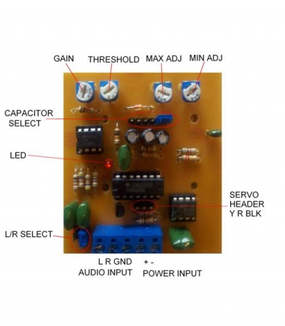
Gain: The gain adjustment is used to control the gain of the amplifier to match the controller to your source audio
Threshold: The threshold adjustment is used to calibrate the circuit and set the point of sound or no sound
Max Adj: The max adjust is used to set the maximum servo position when sound is present. You can think of this like a high limit switch
Min Adj: The min adjust is used to set the minimum servo position when sound is not present. You can think of this like a low limit switch.
Capacitor Select: There are 3 capacitors of different values to chose from. The higher the value of the capacitor the more smooth the jaw will move. If you want a more jerky action enable a lower value capacitor or no capacitor at all. The capacitors are arranged lowest to highest value from left to right. Capacitors are enabled by placing a shunt on the jumpers JP4,JP5,JP6 directly above the capacitors.
LED: The LED lights up when sound is present and is used to aid in setting the threshold adjustment
L/R Select: If you want the board to "Listen" only to the left or right channel of audio install a shunt on either the left or right jumper. If you want it to "listen" to both channels install shunts on both jumpers.
Connections
Audio input: X3 This is where you connect stereo audio to the board. anything from line level to low level speaker should be OK
Power input: X2 4.7-6 VDC is connected here. The current required will depend largely on the servo you are using. This circuit draws very little current check the specs your servo for current requirements
Servo Header: JP3 This is where your servo will connect to the board. Pin#1(yellow) goes to the left when connecting the servo
Setup
1 Turn on the power and remove all audio source. This can be done by removing the L/R select shunts
2 Turn the threshold adjustment clockwise until the circuit trips(the LED will light and the servo will move to the open position)
3 Adjust the MAX adjust to your desired full open position.
4 Slowly turn the threshold adjustment counter-clockwise until the circuit resets(LED will turn off and servo will move to the closed position)
5 Adjust the Min adjustment to your desired full closed position.
6 Add your audio source and adjust the gain as needed to make the circuit trip and reset with the audio
Description of operation
From the Scary Terry website
"As long as there is sound present, the servo will drive to its "max" position. If the sound is short in duration, the servo will not have time to drive to "max" but will drive part way and return to "min" position. While this method of moving a mouth is not perfect, it's pretty good and I'm very happy with the effect. It's important to remember that any sound will drive the servo, voice, music or noise, so if you're trying to make a Bucky mouth move to a voice track, you shouldn't have music in the background of that particular track. There is a way to include music or other sounds and still have the appropriate jaw movement. Jeff Stevens came up with a solution and I include his email at the bottom of this page"
Jeff Stevens solution
"Dear Scary-Terry, I am writing you about a new method for using your audio-servo driver. Here’s how you do it. First, you record your sounds on a two channel cd and player. On one of the channels have the voice and all other audio effects that you want people to hear, such as music or thunder etc. On the other channel, whether it is the left or right it doesn’t matter, you record the sounds that you want to drive the audio-servo driver. You connect this channel to the audio driver. You then use a y-splitter to take the first channel, the one you want people to hear, and connect it to both channels on the amplifier or amplified speakers. You now have the ability to have music without it activating the skull. The effect sounds stereo because it is coming out of two speakers, but both are playing the same thing. That is the only disadvantage. Let me know what you think. -Jeff Stevens"
Threads and Demo Videos
Initial thread
Demo Video 1
Demo Video 2
Demo Video 3 with technique for better sound to motion adjustment using high frequency tones.
Assembly
THE ASSEMBLY INSTRUCTIONS ARE A WORK IN PROGRESS, PLEASE CHECK BACK IN A FEW DAYS WHEN IT IS FINALLY CORRECT
The Simple Sound to Servo is a simple device to assemble and test. It is easiest if you build the units by inserting the various components from smallest to tallest .
- Begin by inspecting the PCBs to look for any defects such as cracks or breaks. The holes on the board should be open on both sides. Then inspect and sort out the various parts for the board.
- Install the resistors:
- Install the 220K ohm resistor (red-red-yellow) at location R9. The resistor is not polarized, so it can go either way.
- Install the 1K ohm resistor (brown-black-red) at location R1. The resistor is not polarized, so it can go either way.
- Install the 47K ohm resistors (yellow-violet-orange) at locations R2 and R4. The resistors are not polarized, so it can go either way.
- Install the 10K ohm resistors (brown-black-orange) at locations R5,R12,R15,R20. The resistors are not polarized, so it can go either way.
- Install the 2.2K ohm resistor (red-red-red) at location R14. The resistor is not polarized, so it can go either way.
- Install the 470 ohm resistor (yellow-violet-brown) at location R8. The resistor is not polarized, so it can go either way.
- Install the 4.7K ohm resistors (yellow-violet-red) at locations R4 and R11. The resistors are not polarized, so it can go either way.
- Install adjustment trimpots:
- Install the 5K ohm trimpot at location R3. The trimpot only fits one way, with the two legs towards the top of the board.
- Install the 1K ohm trimpot at location R6. The trimpot only fits one way, with the two legs towards the top of the board.
- Install the 50K ohm trimpots at locations R10 and R22. The trimpot only fits one way, with the two legs towards the top of the board.
- Install the IC sockets:
- Install the 14 pin IC socket at location IC2. The notch on the socket should face the left side of the board.
- Install the 8 pin IC sockets at locations IC1 and IC3. The notch on the socket should face the left side of the board.
- Install the 1N914 Diode at location D1. The diode is polarized and it can only go one way. The end with the band (cathode) goes towards the right side of the board.
- Install the 2N3904 transistor at location Q1. The flat side of the transistor should face the left side of the board.
- Install the capacitors:
- Install the 2.2uF electrolytic capacitor at location C5. The capacitor is polarized. The side of the capacitor will have a stripe on the negative side. The long lead is the positive side, and it goes in the hole towards the top side of the board.
- Install the 4.7uF electrolytic capacitor at location C2. The capacitor is polarized. The side of the capacitor will have a stripe on the negative side. The long lead is the positive side, and it goes in the hole towards the top side of the board.
- Install the 10uF electrolytic capacitor at location C7. The capacitor is polarized. The side of the capacitor will have a stripe on the negative side. The long lead is the positive side, and it goes in the hole towards the top side of the board.
- Install the 100nF (0.1uF) mylar capacitors at locations C1,C3,C6,C11. The capacitor is not polarized, so it can go either way.
- Install the 10nF (0.01uF) mylar capacitor at location C4. The capacitor is not polarized, so it can go either way.
- Install the red LED at location D2. The LED is polarized. There is a flat side (cathode) has a short lead and it faces towards the left side of the board.
- Install the jumpers:
- Install the 2 pin headers at locations JP1 and JP2. Snap the 2pin header from the longer strip by holding it in pliers and breaking along the lines between the pins. The short side of the jumper strip goes into the board.
- Install the 3 pin header at location JP3. Snap the 3pin header from the longer strip by holding it in pliers and breaking along the lines between the pins. The short side of the jumper strip goes into the board.
- Install the 6 pin header across locations JP4,JP5,JP6. Snap the 6pin header from the longer strip by holding it in pliers and breaking along the lines between the pins. The short side of the jumper strip goes into the board.
- Install the Screw connectors:
- Install the 3 position screw terminal block at location X3. The side where the wires enter under the screw should face the bottom of the board.
- Install the 2 position screw terminal block at location X2. The side where the wires enter under the screw should face the bottom of the board.
- Install the ICs:
- Install the LM1458N IC in the 8 pin socket at location IC1. The notch on the IC should face the left side of the board.
- Install the CD4066 IC in the 14 pin socket at location IC2. The notch on the IC should face the left side of the board.
- Install the NE555 IC in 8 pin socket at location IC3. The notch on the IC should face the left side of the board.
Congratulations, you have just finished building the Simple Sound to Servo! Inspect the board to make sure that you have soldered all connections and that there are no shorts or cold solder joints.
Schematic
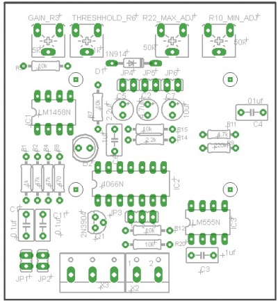
Here is a schematic diagram in pdf format File:Simple Sound to Servo sch.pdf
Board
Currently this is a home etch only circuit board. You can download the needed files to etch your own circuit board from the File Library
BOM
All parts were sourced from Tayda Electronics 1 BOM will populate 2 Simple Sound to Servo Boards. The BOM is a double order because just one does not meet the $5 minimum order. You will also have a few left over resistors due to the fact that Tayda requires minimum of 10 each value. The only part that I have not tested is the 3.5mm audio Jack. This jack was an after though and is meant to be mounted as a pass thru connector on your enclosure that way you don't need to open the enclosure to plug your audio cable in.
Tayda Electronics
| Part | Location | Qty | Part # | Link |
| 220K OHM 1/4W 5% Carbon Film Resistor | R9 | 10 | A-2110 | Link |
| 100nF 0.1uF 100V 5% Mylar Film Capacitor | C1,C3,C6,C11 | 8 | A-4110 | Link |
| 1K OHM 1/4W 5% Carbon Film Resistor | R1 | 10 | A-2123 | Link |
| 47K OHM 1/4W 5% Carbon Film Resistor | R2,R4 | 10 | A-2066 | Link |
| 5K OHM Trimpot Variable Resistor 6mm | R3 | 2 | A-2513 | Link |
| 1K OHM Trimpot Variable Resistor 6mm | R6 | 2 | A-2509 | Link |
| 10K OHM 1/4W 5% Carbon Film Resistor | R5,R12,R15,R20 | 20 | A-2115 | Link |
| 1N914 Small Signal Diode 200mA 100V | D1 | 2 | A-615 | Link |
| LM1458N LM1458 1458 IC DUAL OPERATIONAL AMPLIFIER | IC1 | 2 | A-286 | Link |
| 10uF 25V105C Radial Electrolytic Capacitor 5x11mm | C7 | 2 | A-4534 | Link |
| 2.2K OHM 1/4W 5% Carbon Film Resistor | R14 | 10 | A-2087 | Link |
| CD4066 4066 IC CMOS QUAD BILATERAL SWITCH | IC2 | 2 | A-555 | Link |
| 470 OHM 1/4W 5% Carbon Film Resistor | R8 | 10 | A-2049 | Link |
| 4.7K 4K7 OHM 1/4W 5% Carbon Film Resistor | R4,R11 | 10 | A-2027 | Link |
| 50K OHM Trimpot Variable Resistor 6mm | R10,R22 | 4 | A-2500 | Link |
| 10nF 0.01uF 100V 5% Mylar Film Capacitors | C4 | 2 | A-4106 | Link |
| NE555 IC 555 Timer DIP-8 | IC3 | 2 | A-249 | Link |
| 2.2uF 50V 105C Radial Electrolytic Capacitor 5x11mm | C5 | 2 | A-4532 | Link |
| 4.7uF 16V 105C Radial Electrolytic Capacitor 5x11mm | C2 | 2 | A-4529 | Link |
| 2N3904 NPN General Propose Transistor | Q1 | 2 | A-111 | Link |
| LED 3mm Red | D2, | 2 | A-261 | Link |
| 40 Pin 2.54 mm Single Row Pin Header Strip | JP1,JP2,JP3,JP4,JP5,JP6 | 1 | A-197 | Link |
| DG301 Screw Terminal Block 3 Positions 5mm | X3 | 2 | A-669 | Link |
| DG301 Screw Terminal Block 2 Positions 5mm | X2 | 2 | A-668 | Link |
| 14 pin DIP IC Socket Adaptor Solder Type | IC2 | 2 | A-004 | Link |
| 8 pin DIP IC Socket Adaptor Solder Type | IC1,IC3 | 4 | A-001 | Link |
| 3.5mm Stereo Enclosed Socket | 2 | A-865 | Link |
Total cost for 2 BOMs $5.01
You will also need a few shunts like these from Mouser. Tayda does not carry them or at least I could not find them. I just grab them out of old disc drives and motherboards.
Housing
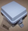
The Simple Sound to Servo was designed to fit in the TA-200 Demarcation Enclosure available from numerous vendors including www.wlcventures.com


