This page is intended to help identify/isolate some of the common problems individuals encounter when building/operating the Renard 64XC controller board.
The troubleshooting procedures provided here are presented in a detailed step-by-step systematic approach. This approach is not necessarily the quickest way to find your problem. If you are looking for a quick fix, then swap anything/everything that you can and come back to these procedures if you are still having problems.
The following procedures require the individual to be familiar with the operation of a digital multimeter (or voltmeter/ohmmeter if you prefer). If you currently do not know how to measure resistance or how to measure voltage, please take some time now an learn these basic skills before attempting these procedures. This website provides some basic information on using multimeters.
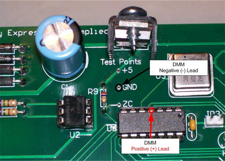
Multimeter Usage Tip
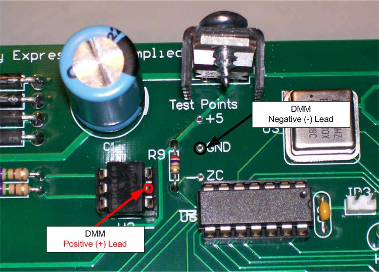
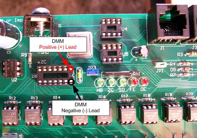
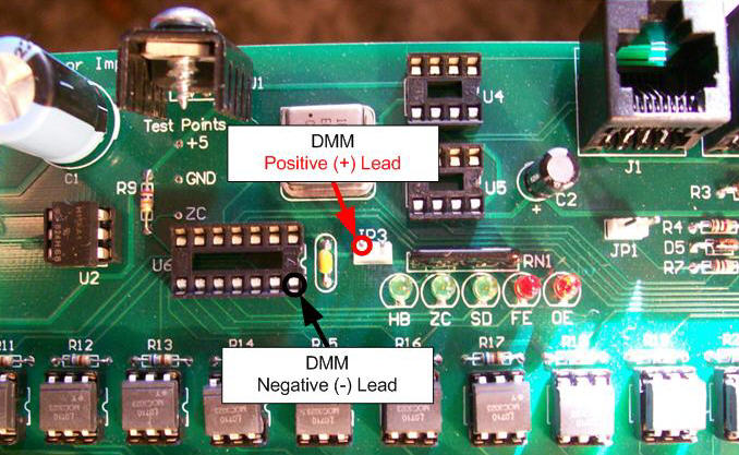
All DC voltages in this document are referenced to GND. So for all measurements, the multimeter negative (-), usually black, lead needs to be connected to a GND point on the PCB. The best location would be the GND Test Point located below U1. The positive lead (+), usually red, gets connected to the location called out in the procedure.
Disclaimers
Due to the nature of the information contained on this page, it is imperative that all individuals read and understand the disclaimers contained here.
Basic Troubleshooting Info
Verify Setup
The first step to successful troubleshooting is to ensure that your setup is correct.
These are the most common problems encountered by individuals who have built Renard SS boards since their debut to the DIYC community:
Missed solder pads or bad solder joints. Many individuals get in a rush when assembling their boards and will occasionally miss a solder pad or just do a poor job on a particular solder pad. This type of problem can usually be easily identified by closely inspecting all the solder pads on the board after assembly is complete. Missed solder pads may/will cause many different problems that will cause you to spend many hours troubleshooting only to find that it was as simple as a missed solder pad. So take your time and closely inspect your solder work when you are done with the assembly. It is strongly suggested that you inspect the joints with a good magnifying glass under really good lighting.
Bad data cable coming from the computer. Many individuals assume that all serial cables are identical, but that is far from the truth. Just because a cable has the correct DE9 connectors on each end doesn’t mean that the wires inside are going to the correct pins for Renard operation. It is always best to physically check the pin continuity to verify that the cable will work for Renard operation. Make sure that your interconnect cable is wired according to the Renard 64XC Controller wiki.
PICs with corrupted firmware or no firmware. This mostly affects individuals who get their PICs from a “group buy” with the firmware already loaded but also does impact those who program their own PICs. For whatever reason, sometimes a PIC (believed to be correctly programmed) will not behave correctly and needs to be re-flashed with the firmware. Once it is re-flashed, it then works correctly. This is why all individuals who are using these boards should invest in a PIC programmer. A programmer will also enable you to switch to the diagnostics firmware, which will help tremendously during troubleshooting. Your best bet is to get the PICKIT2 or PICKIT3 from Microchip.
Incorrect Vixen Settings. It cannot be emphasized enough, the Renard boards will not work correctly if Vixen is not setup correctly. Verify that you have the Vixen plug-in settings correct as compared to the Renard 64XC Controller wiki. The settings in Vixen mus match the setting used in the Renard Firmware burned onto the PICs.
Troubleshooting the Renard 64XC Controller
Troubleshooting Flow
The complete pdf version of this flowchart can be found here
Page 1
Page 2
Page 3
Page 4
Page 5
Troubleshooting Steps
Verify that you have the power/control cables connected correctly as compared to the Renard 64XC Controller wiki.
The complete pdf version of this flowchart can be found here
Troubleshooting Steps
Remove power from the Renard Controller
Disconnect all cables.
If installed, remove all the IC chips from their sockets.
This is to prevent them from being damaged further if you do have power problems.
In normal use, the Renard 64XC does not require a fuse. However, since this section is about "problems", it is prudent to have one installed. The best way to do this is with an in-line fuse holder on the incoming power. Mouser PN#576-150274 (holder) and PN#576-0235.300MXP (fuse) are perfect for this.
File:Transformer Wiring.png
If not installed already, install an appropriate rated fuse in the SSR fuse holder. Use the smallest value fuse that you have available for this portion of testing.
Using a smaller fuse here is for safety during initial power testing. If there are any problems with bad triacs, bridged solder pads or a bad transformer during first power application, a small fuse will blow before any permanent damage to the SSR PCB can occur. For testing one SSRez channel at a time (for example), the recommended fuse size is 1A. This is a standard 5x20mm fuse available most anywhere.
Turn ON the AC Power to the Renard Board
Connect an AC power cable to the SSR terminal block. The 120V neutral line (wide blade on a polarized plug) goes to the N terminal and the 120V hot line goes to the 120V terminal.
If the voltage is now correct but was low or missing in step 16 or blew the fuse at initial turn-on, possible problems could be:
Bad transformer (shorted primary)
Bad/shorted triac
Shorted/bad solder connection(s)
Carefully inspect the board for any possible problems with the solder connections. Fix any possible problems and then restart the troubleshooting process.
After other attempts to fix the problem have failed, the last resort would be to remove each triac and the transformer til good power was seen with F1 installed.
If you have gotten to this step, then your board has good +5 VDC and the PWR LED turns ON when AC power is applied without any of the IC chips installed.
If this is incorrect, restart the troubleshooting process.
Turn OFF AC power
Install one of the IC chips into its respective socket.
Turn ON AC power
Did the PWR LED light?
If it did not, then the last IC chip installed is bad and needs to be replaced.
If it did, then repeat steps 22(??) thru 25(??) until all IC chips are installed.
Your Renard board should now have all the IC chips installed and have good DC power on the board.
The Renard Diagnostic Firmware should now be blinking the HB LED (channel 2) and ZC LED (channel 5). All other channels/LEDs should be OFF.
If the ZC LED (channel 5) is not blinking:
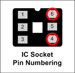
Measure voltage at U6 pin 4 or U2 pin 5, should only be approximately .3 VDC. If you have an oscilloscope, you should see a signal like the purple trace in this image.
If voltage is around 5.0 VDC , then the ZC is not working. Possible solutions:
Replace U2
Check the values of R1 & R2
Check the solder pads on all the above components
If you have gotten to this step, then your board appears to be functioning correctly so far. Now it is time to see if it will communicate with the computer.
REMINDER: Make sure that Vixen is configured correctly before attempting the next step. The settings for the Renard Dimmer Plug-In should be set as shown on The Renard SS24 Controller Board wiki page.
Run a Vixen sequence
NOTE: Vixen only sends out data when there is a change in event data. So make sure that the test sequence you are using has frequent changes in the event data..
SD LED will be ON whenever Vixen sends data to the Renard SS24. The FE and OE LEDs should remain OFF.
If this is correct, then your Renard SS24 has passed the diagnostics test.
If the SD LED was ON and either or both the FE or OE LED came ON, then double check the Renard Dimmer plug-in settings in Vixen and retry.
If no LEDs were lit in step 20, then it seems that you are not getting any data from the computer. Try the following:
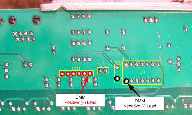
If correct, then probably all the LEDs are installed backwards
If incorrect, replace RN1
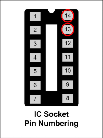
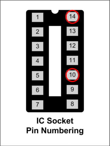
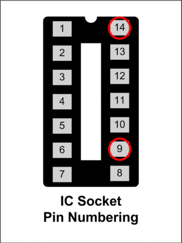
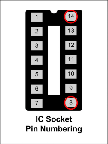
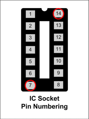
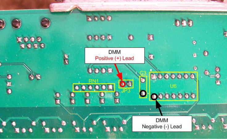
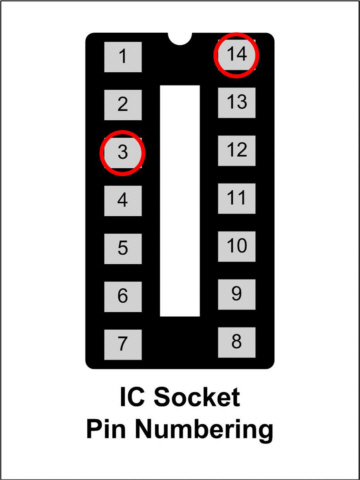
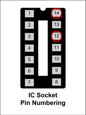
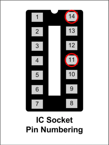
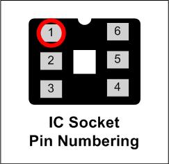
If any (but not all) of the LEDs in steps 6 thru 10 did not light, measure the DC voltage at the appropriate location on the IC socket for U6. The voltage measured at each location should be approximately 3.0-3.5 VDC.
If any voltage measured in step 13 was 0 VDC, then most probably the associated LED is installed backwards.
If any voltage measured in step 13 was 5 VDC, then most probably the solder pads for the associated LED are bridged.
Troubleshooting SSR Circuitry Problems
Symptom(s):
Channel remains on constantly
Channel does not come on when commanded
Triac gate resistor burnt/blown
Possible Problem(s):
Bad triac
Triac in Backwards
Bad opto
Opto/MOC in Backwards
Bad/missed Solder Joints
Troubleshooting Flow
Troubleshooting Steps
Turn OFF AC power
Are any of the triac gate resistors (R34-R57) burnt/blown/damaged?
If so, replace that resistor and check the solder pads on the associated triac. Blown gate resistors are usually caused by a missed solder connection on the triac.
Are channels 13 thru 24 bad? If they are,
Check the right side fuse
Check the power connection to the right side of the board
Check the solder pads on the right side fuse holder
Is the problem in channels 1 thru 8?
If not, go to step 21
Remove PIC chip U6
If installed, remove the shunt (jumper) on JP3.
If not already installed, attach some test lights to the terminal block of the failing channel.
Turn ON AC power
Test lights should be OFF
If the test lights are ON, go to step 53
Using the following table, momentarily use a jumper to turn ON the test lights
Test lights should come ON when the jumper is connected to the locations in the table
Does the previously bad channel now work? If it does:
Turn OFF AC power
Install PIC chip U6
Begin testing again where previous failure was noted
Turn OFF AC power
Replace the opto (M1-M8) controlling the bad channel
Return to step 8 and repeat tests with the new opto
Continue here if replacing the opto did not fix the problem
Turn OFF AC power
Remove the opto (M1-M8) controlling the bad channel
Turn ON AC power
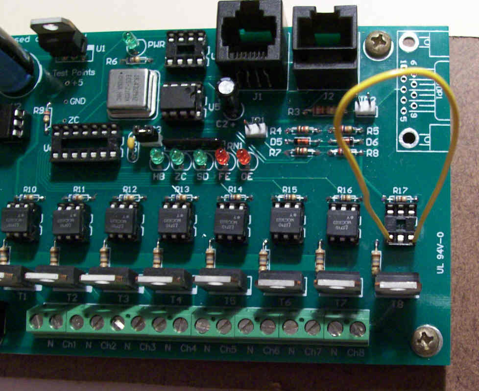
SAFETY NOTICE: In the following step you will be using a jumper wire (small piece of insulated wire) to jump 120 VAC from one pin to another. You need to be very sure that you know what pins you are putting the jumper to before you proceed. Applying 120 VAC to the wrong location could/can cause some very undesirable results..
If incorrect, check the current limiting resistor (R10-R17) associated with that opto. You should be able to read approx 5 VDC on both sides of the resistor.
If correct, then something must have been overlooked during the troubleshooting process. Turn OFF the AC power and reinstall any removed components, then restart the troubleshooting process.
Is the problem in channels 9 thru 16?
If not, go to step 37
Remove PIC chip U7
If not already installed, attach some test lights to the terminal block of the failing channel.
Turn ON AC power
Test lights should be OFF
If the test lights are ON, go to step 53
Using the following table, momentarily use a jumper to turn ON the test lights
Test lights should come ON when the jumper is connected to the locations in the table
Does the previously bad channel now work? If it does:
Turn OFF AC power
Install PIC chip U7
Begin testing again where previous failure was noted
Turn OFF AC power
Replace the opto (M9-M16) controlling the bad channel
Return to step 24 and repeat tests with the new opto
Continue here if replacing the opto did not fix the problem
Turn OFF AC power
Remove the opto (M9-M16) controlling the bad channel
Turn ON AC power
SAFETY NOTICE: In the following step you will be using a jumper wire (small piece of insulated wire) to jump 120 VAC from one pin to another. You need to be very sure that you know what pins you are putting the jumper to before you proceed. Applying 120 VAC to the wrong location could/can cause some very undesirable results..
If incorrect, check the current limiting resistor (R18-R25) associated with that opto. You should be able to read approx 5 VDC on both sides of the resistor.
If correct, then something must have been overlooked during the troubleshooting process. Turn OFF the AC power and reinstall any removed components, then restart the troubleshooting process.
Is the problem in channels 17 thru 24?
If not, then your Renard SS24 should be operational.
Remove PIC chip U8
If not already installed, attach some test lights to the terminal block of the failing channel.
Turn ON AC power
Test lights should be OFF
If the test lights are ON, go to step 53
Using the following table, momentarily use a jumper to turn ON the test lights
Test lights should come ON when the jumper is connected to the locations in the table
Does the previously bad channel now work? If it does:
Turn OFF AC power
Install PIC chip U8
Begin testing again where previous failure was noted
Turn OFF AC power
Replace the opto (M17-M24) controlling the bad channel
Return to step 40 and repeat tests with the new opto
Continue here if replacing the opto did not fix the problem
Turn OFF AC power
Remove the opto (M17-M24) controlling the bad channel
Turn ON AC power
SAFETY NOTICE: In the following step you will be using a jumper wire (small piece of insulated wire) to jump 120 VAC from one pin to another. You need to be very sure that you know what pins you are putting the jumper to before you proceed. Applying 120 VAC to the wrong location could/can cause some very undesirable results..
If incorrect, check the current limiting resistor (R26-R33) associated with that opto. You should be able to read approx 5 VDC on both sides of the resistor.
If correct, then something must have been overlooked during the troubleshooting process. Turn OFF the AC power and reinstall any removed components, then restart the troubleshooting process.
Turn OFF AC power
Remove the opto (M1-M24) controlling the bad channel
Turn ON AC power
Is the test light still ON?
If the light is still ON then it could be either a bad triac or possibly a bridged solder joint on the triac, opto socket, triac gate resistor or the terminal block.
If the light is OFF, then replace the opto with a new one and retest


