24 Channel Renard with SSR Assembly Instructions
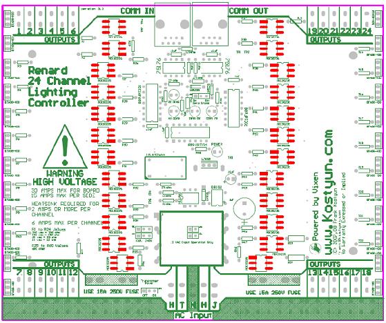
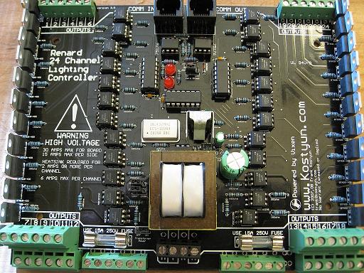
Revision 1 board (first revision) Revision 2 board (second revision) Revision 2.5 board (final revision)
Schematic
Media:Renard64_sch_001.pdf (please note, the schematic is identical to the Renard64)
Layout
COOP PCB V2.5
BOM
PCB
1  TBA                   Renard 24-Port PCB

511-BTA08-400B 24
579-PIC16F688-I/P 3
571-7969494 1
595-SN75176BP 2
511-L7805CV 1
821-DB102G 1
571-2828376 4
271-680-RC 28
532-7136DG 1
271-180-RC 24
271-27K-RC 3
271-1K-RC 4
571-5564161 2
271-120-RC 1
859-MOC3023 24
625-1N4001-E3 1
78-1N5239B 3
838-3FD-320 1
782-H11AA1 1
520-TCF1843-X 1
140-HTRL25V1000-RC 1
140-HTRL25V10-RC 1
140-HTRL16V100-RC 1
534-3517 4
504-GMA-15 2

Also need:
5 .1uF capacitors
4 3 pin headers
4 .100 shunts
3 LED's
- NOTE UPDATED 10/06 - I put the wrong transformer part # please see here if you purchased any.
Design Notes
Pin 1 of the crystal is on the bottom left.
Pin 1 of the transformer is on the top left.
The anode pin of the 1N4001 diode is on the top.
The correct designation of the capacitor on the top right is .1uF, not .1F.
The + pin of the DB102 is on the bottom right both of the ~ should be on the left.
Revision History
 1/20/2007 Initial Design
 3/20/2007 Revision 2 submitted to test manufacturing.
 7/15/2007 Changed RJ45 to comply with current Renard standards.
 7/15/2007 Added additional holes for a larger transformer.
 7/15/2007 Added transformer voltage selection jumpers, will allow for 120/240v operation.
 7/15/2007 Changed fuse size to 5x20mm fuse from AG3 fuse.
 7/16/2007 Added option for DIP or SMT MOC2032 optos.
 8/20/2007 Version 2.5 submitted to test manufacturing.
Errata for Rev 1 PCB -
 1) Onboard regulator not functioning properly: needed addition of 1000uF capacator.
 2) Outputs are out of order.
 3) Triacs are located to close together.
Errata for Rev 2 PCB -
 1) Outputs 17/18 are swapped.
 2) RS485 traces swapped.

