File list
Jump to navigation
Jump to search
This special page shows all uploaded files.
| Date | Name | Thumbnail | Size | User | Description | Versions |
|---|---|---|---|---|---|---|
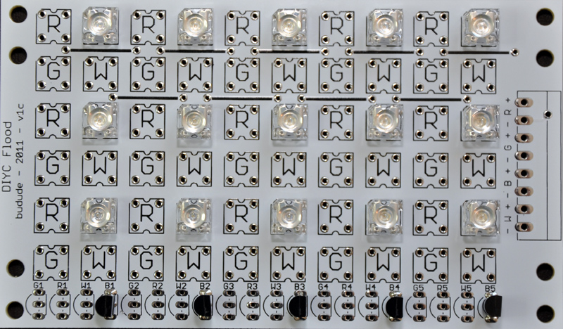
| 14:12, 7 October 2011 | DIYCFlood v1c 2.jpg (file) |  |
267 KB | Jklingert (talk | contribs) | 1 | |
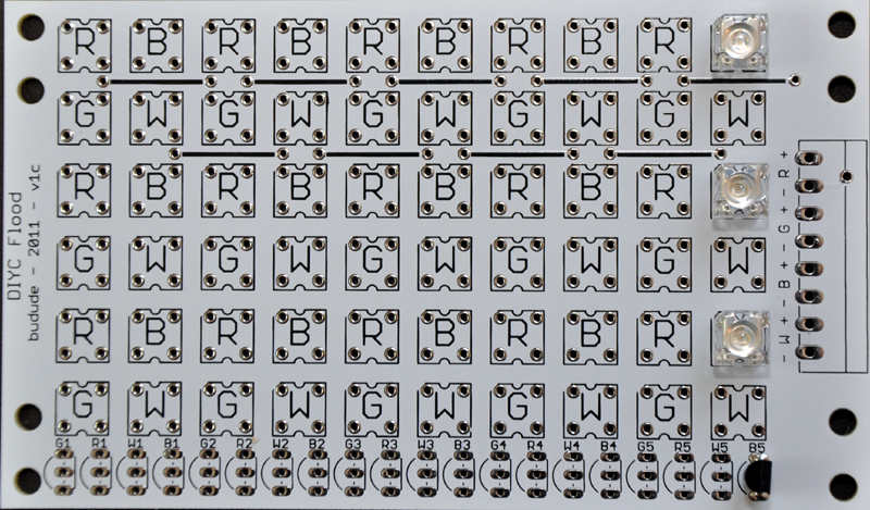
| 14:09, 7 October 2011 | DIYCFlood v1c 1.jpg (file) |  |
274 KB | Jklingert (talk | contribs) | 1 | |
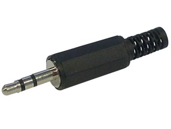
| 03:30, 7 October 2011 | 3.5mm stereo plug.jpg (file) |  |
24 KB | Ukewarrior (talk | contribs) | 1 | |
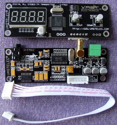
| 18:36, 5 October 2011 | Vastbeauty shot 3.JPG (file) |  |
119 KB | Ukewarrior (talk | contribs) | 2 | |
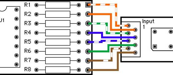
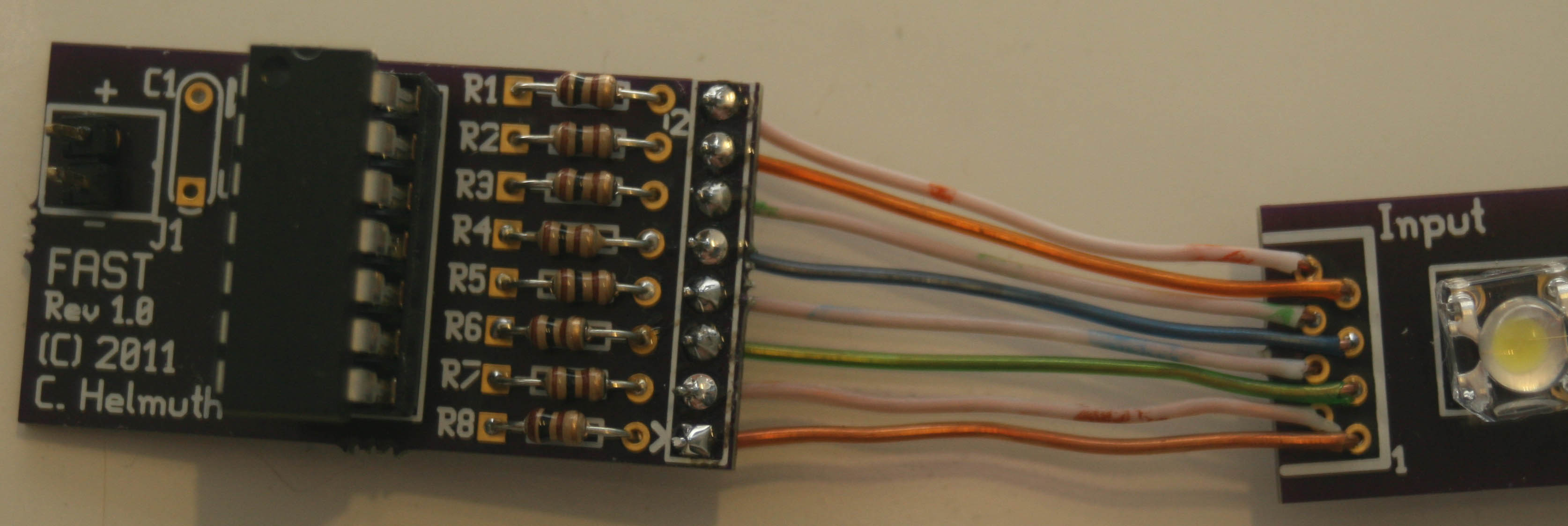
| 01:16, 5 October 2011 | FAST-wiring2.jpg (file) |  |
26 KB | Dmcole (talk | contribs) | Diagram showing how the FAST controller is wired to the FAST LED boards. | 1 |
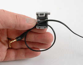
| 03:07, 4 October 2011 | Ferrite 2.jpg (file) |  |
24 KB | Ukewarrior (talk | contribs) | 1 | |
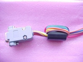
| 03:03, 4 October 2011 | Ferrite 1.jpg (file) |  |
33 KB | Ukewarrior (talk | contribs) | 1 | |
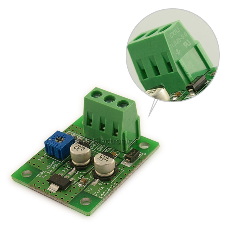
| 00:57, 1 October 2011 | Sure electronics voltage regulator.jpg (file) |  |
69 KB | Ukewarrior (talk | contribs) | 1 | |
| 12:47, 30 September 2011 | FM02 cutout layout.pdf (file) | 6 KB | Ukewarrior (talk | contribs) | 2 | ||
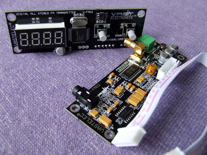
| 02:07, 30 September 2011 | Fm02 beauty shot 3.jpg (file) |  |
221 KB | Ukewarrior (talk | contribs) | 1 | |
| 19:02, 29 September 2011 | Fm02 beauty shot 2.jpg (file) |  |
151 KB | Ukewarrior (talk | contribs) | 1 | |
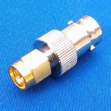
| 14:26, 29 September 2011 | FM02 sma to BNC converter.jpg (file) |  |
35 KB | Ukewarrior (talk | contribs) | 1 | |
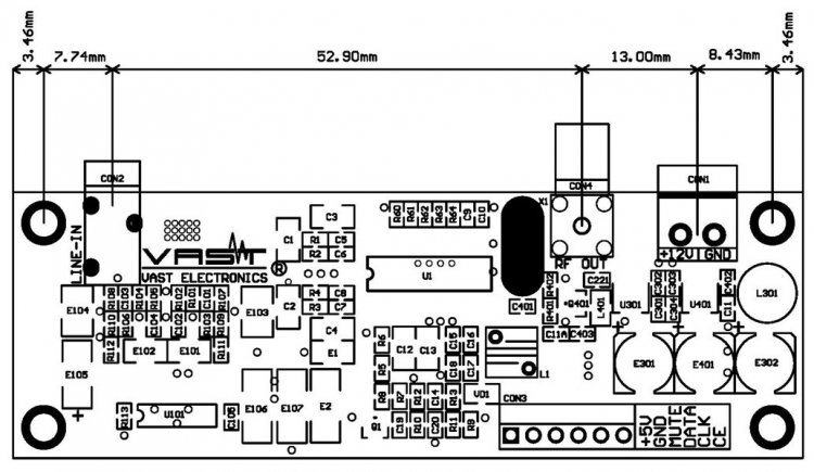
| 13:32, 29 September 2011 | Vast transmitter layout component board.jpg (file) |  |
76 KB | Ukewarrior (talk | contribs) | 1 | |
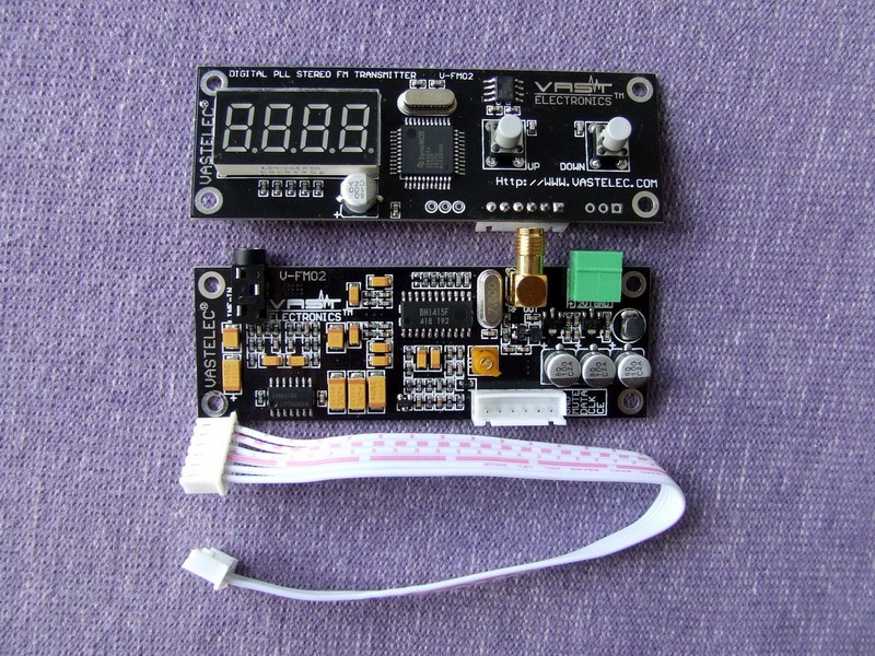
| 02:38, 29 September 2011 | FM02 beauty shot.jpg (file) |  |
172 KB | Ukewarrior (talk | contribs) | Nice picture of the FM-02 | 1 |
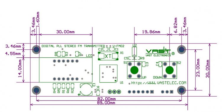
| 02:33, 29 September 2011 | VAST FM-02 Display Board Dimensions.jpg (file) |  |
48 KB | Ukewarrior (talk | contribs) | detailed layout of the Display Board | 1 |
| 00:02, 27 September 2011 | FAST Snowfall Tube Segment (Diag) 20110926.asm (file) | 12 KB | Chelmuth (talk | contribs) | Diagnostic Software Lights 1 LED at a time for about 2 Seconds. | 1 | |
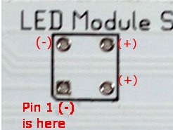
| 21:24, 20 September 2011 | FAST-LED-orientation.jpg (file) |  |
11 KB | Dmcole (talk | contribs) | Illustrates how LED must be oriented on FAST PCBs. | 1 |
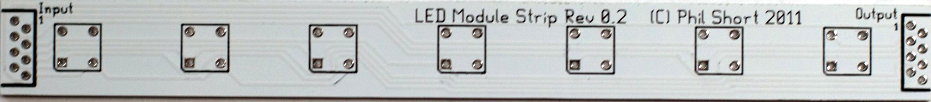
| 19:41, 15 September 2011 | FAST-Segment-PCB1.jpg (file) | 156 KB | Jklingert (talk | contribs) | 1 | ||
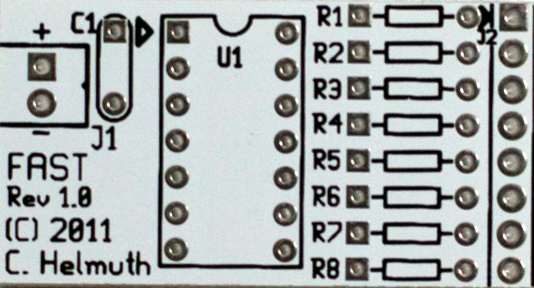
| 19:39, 15 September 2011 | FAST-Controller-PCB1.jpg (file) |  |
121 KB | Jklingert (talk | contribs) | 1 | |
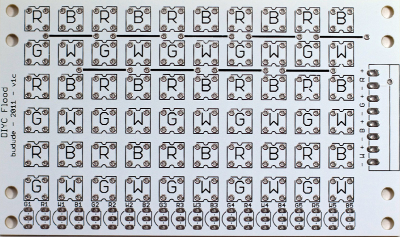
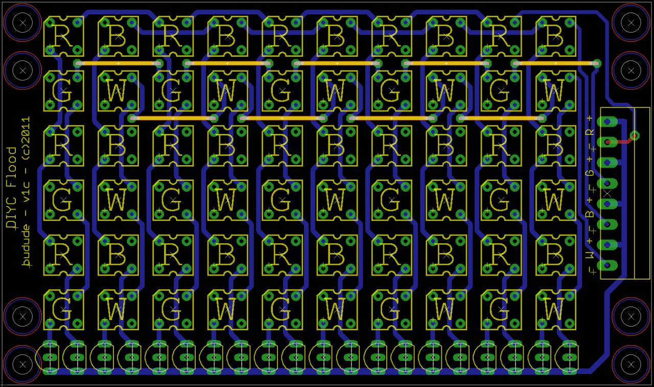
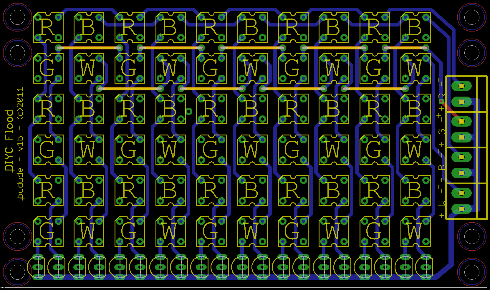
| 19:35, 15 September 2011 | DIYC-Flood-v1c-PCB1.jpg (file) |  |
318 KB | Jklingert (talk | contribs) | 1 | |
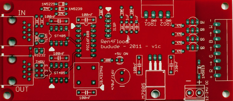
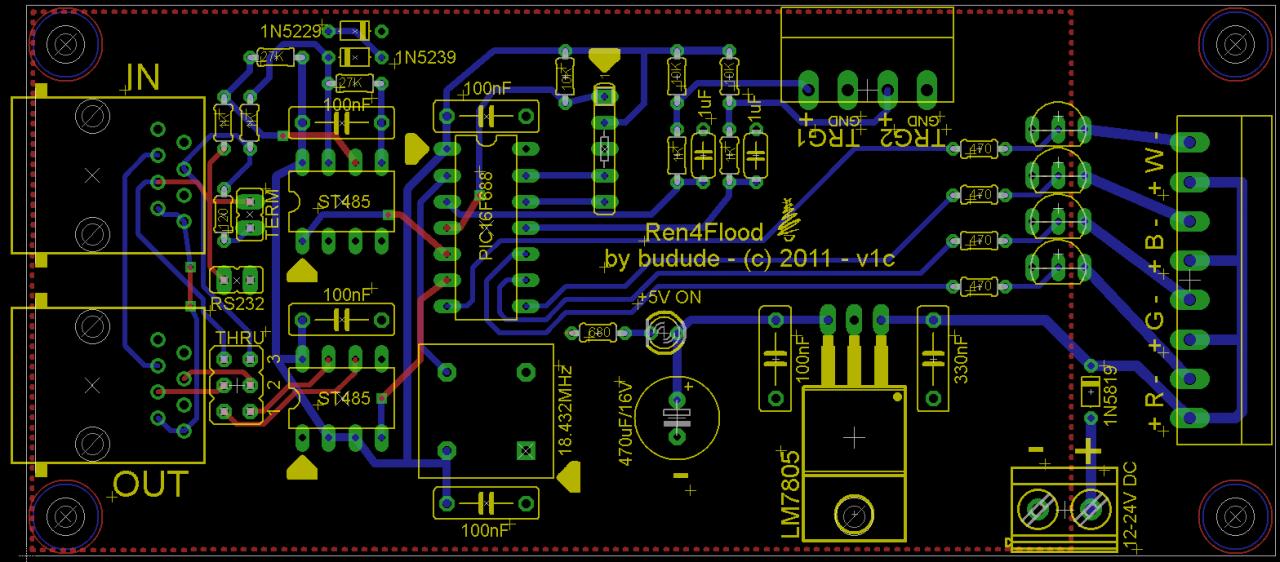
| 19:24, 15 September 2011 | Ren4Flood-v1c-PCB1.jpg (file) |  |
210 KB | Jklingert (talk | contribs) | 1 | |
| 05:42, 2 September 2011 | Pickit ad hoc socket.gif (file) |  |
197 KB | Budude (talk | contribs) | 2 | |
| 18:12, 19 August 2011 | LED Segment.png (file) | 7 KB | Chelmuth (talk | contribs) | 3 | ||
| 18:00, 19 August 2011 | FAST Controller.png (file) |  |
16 KB | Chelmuth (talk | contribs) | Changed the Rev2.0 | 3 |
| 17:57, 8 August 2011 | Ren4Flood-v1c.jpg (file) |  |
137 KB | Jklingert (talk | contribs) | 1 | |
| 17:55, 8 August 2011 | DIYC-Flood-v1c.jpg (file) |  |
234 KB | Jklingert (talk | contribs) | 1 | |
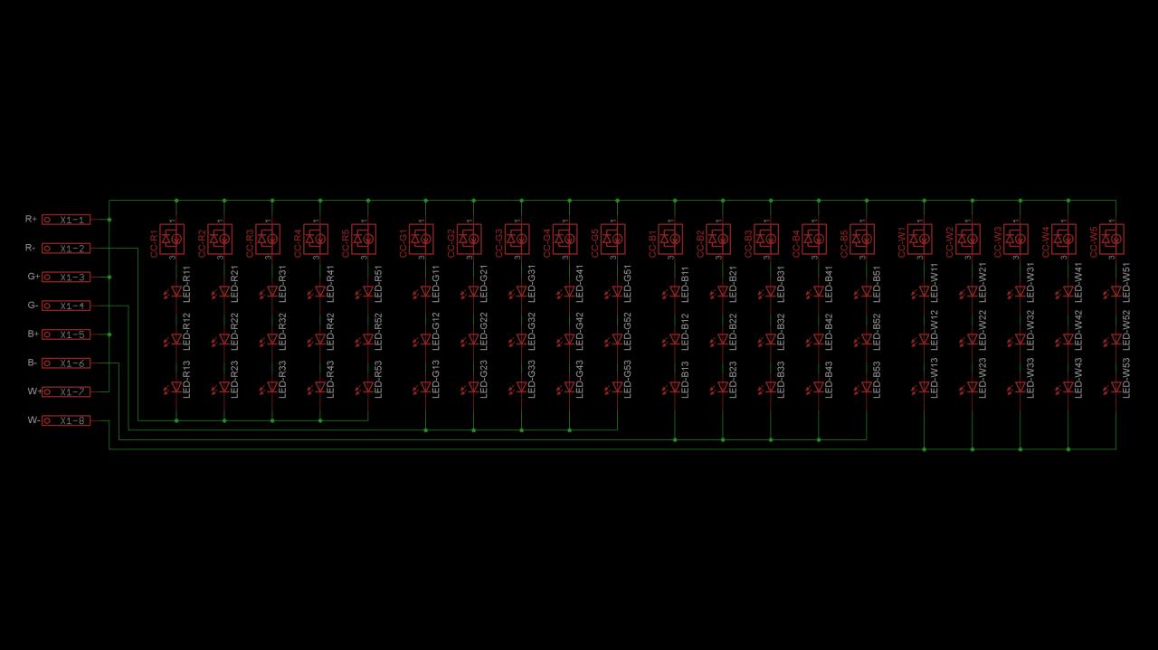
| 23:28, 7 August 2011 | DIYC Flood Schematic1.jpg (file) |  |
63 KB | Jklingert (talk | contribs) | 1 | |
| 23:23, 7 August 2011 | DIYC Flood 1.png (file) |  |
132 KB | Jklingert (talk | contribs) | 1 | |
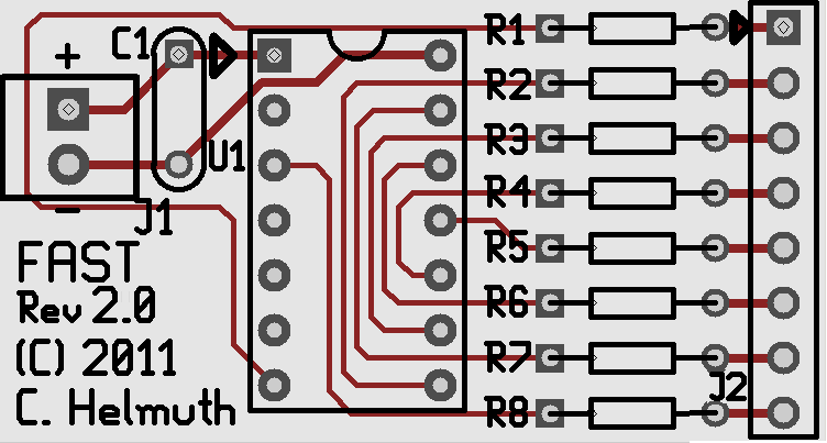
| 22:31, 5 August 2011 | FAST Controller SCH.jpg (file) |  |
51 KB | Chelmuth (talk | contribs) | 3 | |
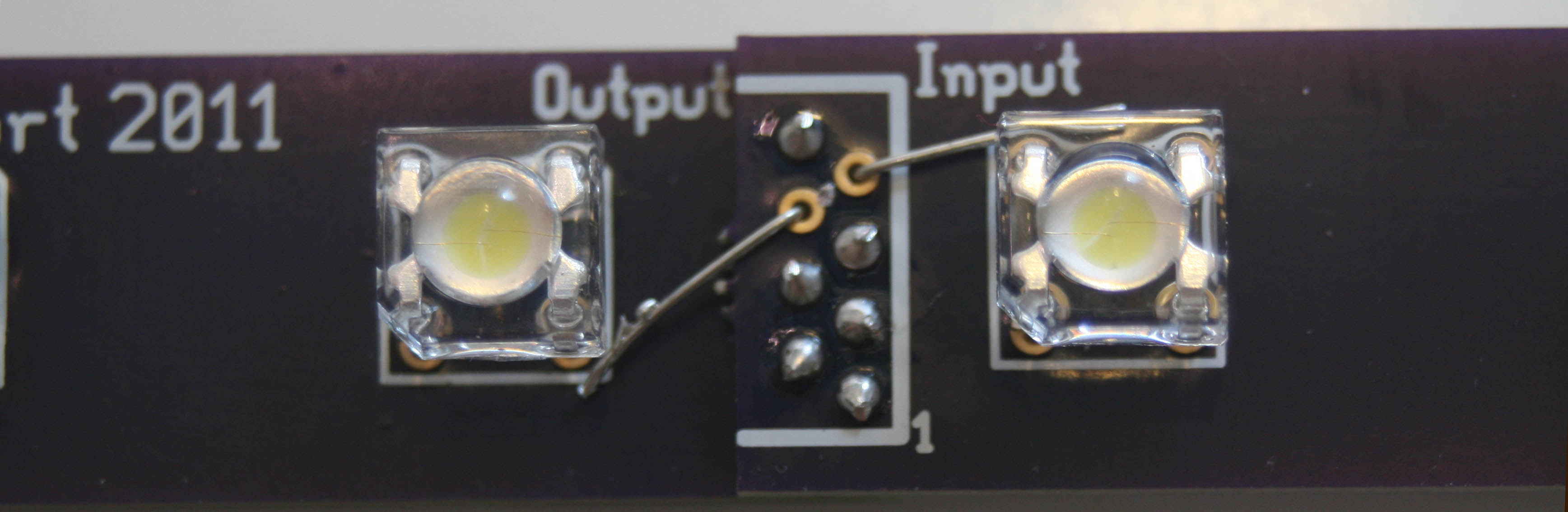
| 21:32, 5 August 2011 | Connection Top.jpg (file) |  |
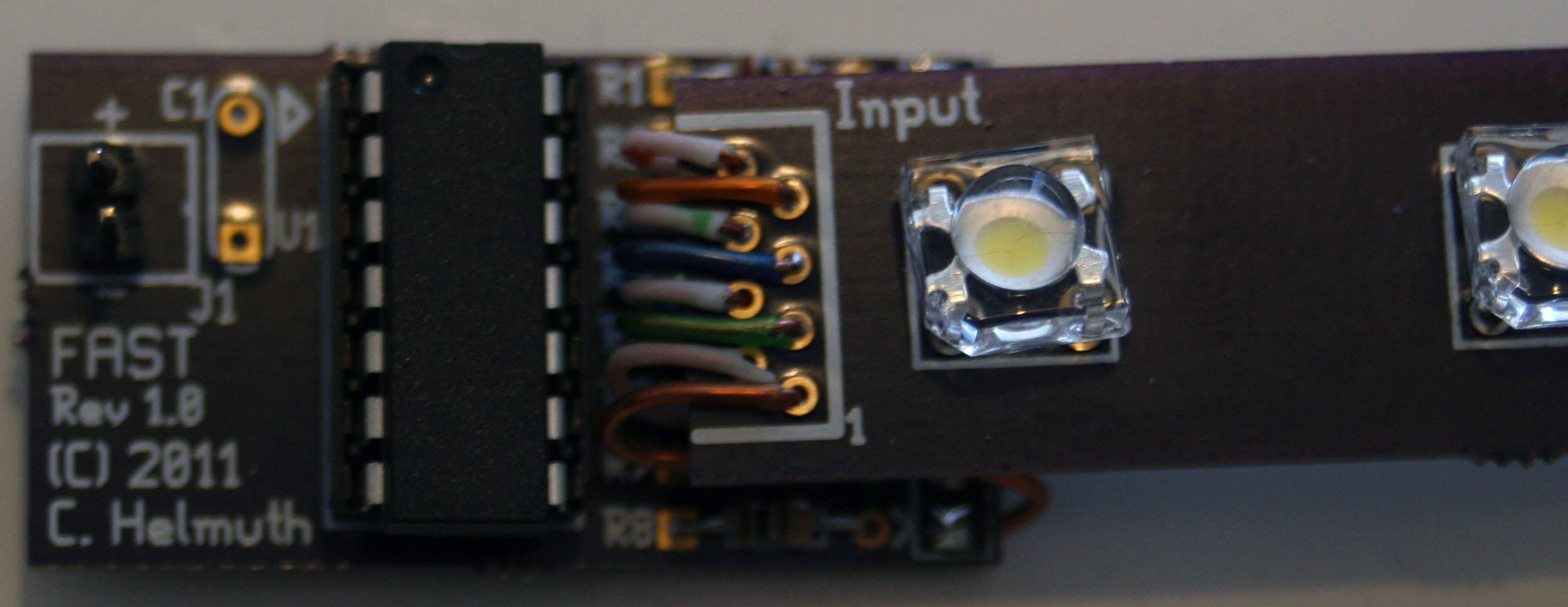
173 KB | Chelmuth (talk | contribs) | Controller To Segment Connection Top View | 1 |
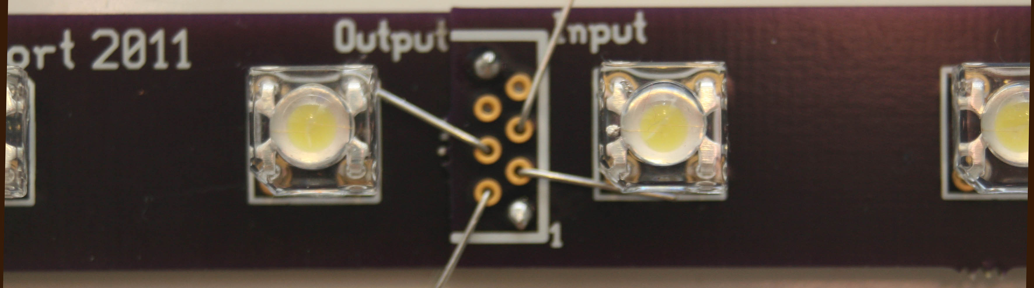
| 21:32, 5 August 2011 | Connection Side.jpg (file) |  |
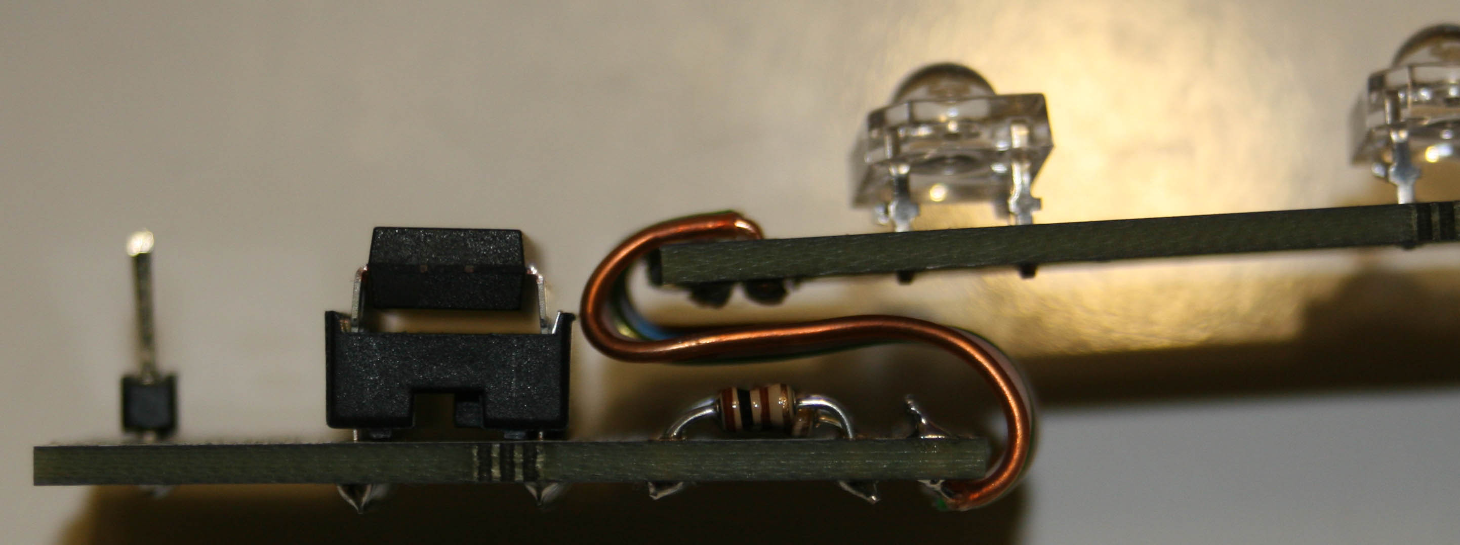
187 KB | Chelmuth (talk | contribs) | Controller To Segment Connection Side View | 1 |
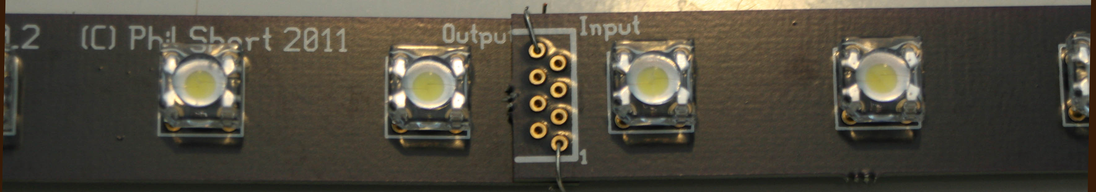
| 00:52, 5 August 2011 | Clips 3.jpg (file) |  |
238 KB | Chelmuth (talk | contribs) | Connecting Segments Together With Resistors Lead Clippings Step 3 | 1 |
| 00:52, 5 August 2011 | Clips 2.jpg (file) |  |
224 KB | Chelmuth (talk | contribs) | Connecting Segments Together With Resistors Lead Clippings Step 2 | 1 |
| 00:51, 5 August 2011 | Clips 1.jpg (file) | 172 KB | Chelmuth (talk | contribs) | Connecting Segments Together With Resistors Lead Clippings Step 1 | 1 | |
| 00:51, 5 August 2011 | Build-05.jpg (file) |  |
247 KB | Chelmuth (talk | contribs) | Controller Connected to Segment | 1 |
| 00:50, 5 August 2011 | Build-02.jpg (file) |  |
229 KB | Chelmuth (talk | contribs) | Socket Soldered | 1 |
| 00:50, 5 August 2011 | Build-01.jpg (file) |  |
353 KB | Chelmuth (talk | contribs) | Resistors Soldered | 1 |
| 00:24, 5 August 2011 | LEDSegmentProto.jpg (file) | 33 KB | Chelmuth (talk | contribs) | 1 | ||
| 00:23, 5 August 2011 | LEDSegmenProto.jpg (file) | 33 KB | Chelmuth (talk | contribs) | 1 | ||
| 00:22, 5 August 2011 | FASTProto sm.jpg (file) |  |
114 KB | Chelmuth (talk | contribs) | 1 | |
| 00:19, 5 August 2011 | FASTProto.jpg (file) |  |
400 KB | Chelmuth (talk | contribs) | Fast Controller Prototype Board | 2 |
| 00:02, 5 August 2011 | FAST With Tail (Modular Wiring) 20110804.asm (file) | 18 KB | Chelmuth (talk | contribs) | 1 | ||
| 21:47, 4 August 2011 | FAST Snowfall Tube With Tail (Modular Wiring).asm (file) | 18 KB | Chelmuth (talk | contribs) | FAST Modular .ASM | 1 | |
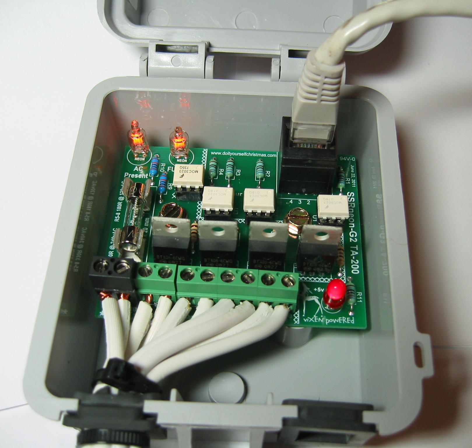
| 03:22, 20 July 2011 | Ssrneon 001.jpg (file) |  |
745 KB | Ukewarrior (talk | contribs) | SSRneon G2 plugged in | 1 |
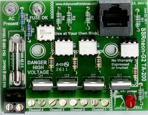
| 18:45, 19 July 2011 | SSRneon G2 BUILT.jpg (file) |  |
210 KB | Ukewarrior (talk | contribs) | 1 | |
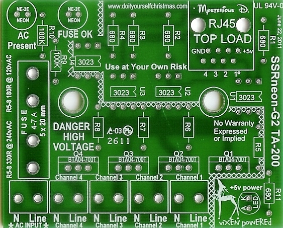
| 16:34, 19 July 2011 | SSRneon G2 PCB.jpg (file) |  |
242 KB | Ukewarrior (talk | contribs) | SSRneon G2 PCB | 1 |
| 19:33, 23 June 2011 | SSRneon-G2 all print.jpg (file) |  |
39 KB | Ukewarrior (talk | contribs) | 1 | |
| 19:30, 23 June 2011 | SSRneon G2 etch silkscreen.pdf (file) | 20 KB | Ukewarrior (talk | contribs) | 1 | ||
| 19:19, 23 June 2011 | SSRneon G2 etch.pdf (file) | 11 KB | Ukewarrior (talk | contribs) | 1 | ||
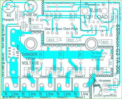
| 19:17, 23 June 2011 | SSRneon-G2 wiki etch.jpg (file) |  |
16 KB | Ukewarrior (talk | contribs) | 1 |