Assembly Instructions The Renard SS24: Difference between revisions
m (→Board Assembly) |
|||
| (37 intermediate revisions by 2 users not shown) | |||
| Line 2: | Line 2: | ||
:The following sequence of steps is by no means the only way to | :The following sequence of steps is by no means the only way to assemble the Renard SS24. It is simply a suggested order of events to achieve the desired goal. | ||
| Line 16: | Line 16: | ||
| | | | ||
* Start by checking the PCB over for any obvious production faults. Check for traces that end abruptly or have cracks/breaks in them. Also check that all holes are clear. | * '''1''' - Start by checking the PCB over for any obvious production faults. Check for traces that end abruptly or have cracks/breaks in them. Also check that all holes are clear. | ||
|| [[Image:Wiki - Renard SS24 PCB.jpg | 200px]] | || [[Image:Wiki - Renard SS24 PCB.jpg | 200px]] | ||
|- | |- | ||
| | | | ||
* Install four diodes D1 thru D4 (PN# | * '''2''' - Install four diodes D1 thru D4 (PN# 511-1N5817). The diodes will have a silver/grey stripe on a black body. Make sure that this stripe lines up with the stripe on the PCB silk screen (to the left). | ||
|| [[Image:Wiki - Renard SS24 Assembly Step02.jpg | 200px]] | || [[Image:Wiki - Renard SS24 Assembly Step02.jpg | 200px]] | ||
|- | |- | ||
| | | | ||
* Install two 750 ohm resistors R1 & R2 (PN# 291-750-RC). Make sure that the resistors have a value of 750 ohms (violet/green/brown/gold stripes). These resistors have no polarity to worry about. | * '''3''' - Install two 750 ohm resistors R1 & R2 (PN# 291-750-RC). Make sure that the resistors have a value of 750 ohms (violet/green/brown/gold stripes). These resistors have no polarity to worry about. | ||
|| [[Image:Wiki - Renard SS24 Assembly Step03.jpg | 200px]] | || [[Image:Wiki - Renard SS24 Assembly Step03.jpg | 200px]] | ||
|- | |- | ||
| | | | ||
* Install the 120 ohm resistor R3 (PN# 291-120-RC). Make sure that the resistor has a value of 120 ohms (brown/red/brown/gold stripes). This resistor have no polarity to worry about. | * '''4''' - Install the 120 ohm resistor R3 (PN# 291-120-RC). Make sure that the resistor has a value of 120 ohms (brown/red/brown/gold stripes). This resistor have no polarity to worry about. | ||
|| [[Image:Wiki - Renard SS24 Assembly Step04.jpg | 200px]] | || [[Image:Wiki - Renard SS24 Assembly Step04.jpg | 200px]] | ||
|- | |- | ||
| | | | ||
* Install two 1K ohm resistors R4, R7 (PN# 299-1K-RC). Make sure that the resistors have a value of 1K ohm (brown/black/red/gold stripes). These resistors have no polarity to worry about. | * '''5''' - Install two 1K ohm resistors R4, R7 (PN# 299-1K-RC). Make sure that the resistors have a value of 1K ohm (brown/black/red/gold stripes). These resistors have no polarity to worry about. | ||
|| [[Image:Wiki - Renard SS24 Assembly Step05.jpg | 200px]] | || [[Image:Wiki - Renard SS24 Assembly Step05.jpg | 200px]] | ||
|- | |- | ||
| | | | ||
* Install three 27K ohm resistors R5, R8, R9 (PN# 299-27K-RC). Make sure that the resistors have a value of 27K ohms (red/violet/orange/gold stripes). These resistors have no polarity to worry about. | * '''6''' - Install three 27K ohm resistors R5, R8, R9 (PN# 299-27K-RC). Make sure that the resistors have a value of 27K ohms (red/violet/orange/gold stripes). These resistors have no polarity to worry about. | ||
|| [[Image:Wiki - Renard SS24 Assembly Step06.jpg | 200px]] | || [[Image:Wiki - Renard SS24 Assembly Step06.jpg | 200px]] | ||
|- | |- | ||
| | | | ||
* Install zener diode D5 (PN# 78-1N5229B). The diode must be installed correctly. The diode should have a black stripe on the orange/red body. Make sure that this stripe lines up with the stripe on the PCB silkscreen (to the left). | * '''7''' - Install zener diode D5 (PN# 78-1N5229B). The diode must be installed correctly. The diode should have a black stripe on the orange/red body. Make sure that this stripe lines up with the stripe on the PCB silkscreen (to the left). | ||
|| [[Image:Wiki - Renard SS24 Assembly Step07.jpg | 200px]] | || [[Image:Wiki - Renard SS24 Assembly Step07.jpg | 200px]] | ||
|- | |- | ||
| | | | ||
* Install zener diode D6 (PN# 78-1N5239B). The diode must be installed correctly. The diode should have a black stripe on the orange/red body. Make sure that this stripe lines up with the stripe on the PCB silkscreen (to the right). | * '''8''' - Install zener diode D6 (PN# 78-1N5239B). The diode must be installed correctly. The diode should have a black stripe on the orange/red body. Make sure that this stripe lines up with the stripe on the PCB silkscreen (to the right). | ||
|| [[Image:Wiki - Renard SS24 Assembly Step08.jpg | 200px]] | || [[Image:Wiki - Renard SS24 Assembly Step08.jpg | 200px]] | ||
|- | |- | ||
| | | | ||
* Install 25 680 ohm resistors R6, R10 thru R33 (PN# 299-680-RC). Make sure that the resistors have a value of 680 ohms (blue/grey/brown/gold stripes). These resistors have no polarity to worry about. | * '''9''' - Install 25 680 ohm resistors R6, R10 thru R33 (PN# 299-680-RC). Make sure that the resistors have a value of 680 ohms (blue/grey/brown/gold stripes). These resistors have no polarity to worry about. | ||
|| [[Image:Wiki - Renard SS24 Assembly Step09.jpg | 200px]] | || [[Image:Wiki - Renard SS24 Assembly Step09.jpg | 200px]] | ||
|- | |- | ||
| | | | ||
* Install 24 180 ohm resistors R34 thru R57 (PN# 291-180-RC). Make sure that the resistors have a value of 180 ohms (brown/grey/brown/gold stripes). These resistors have no polarity to worry about. | * '''10''' - Install 24 180 ohm resistors R34 thru R57 (PN# 291-180-RC). Make sure that the resistors have a value of 180 ohms (brown/grey/brown/gold stripes). These resistors have no polarity to worry about. | ||
|| [[Image:Wiki - Renard SS24 Assembly Step10.jpg | 200px]] | || [[Image:Wiki - Renard SS24 Assembly Step10.jpg | 200px]] | ||
|- | |- | ||
| | | | ||
* Install three 0.1uF capacitors C3, C4 & C5 (PN# 80-C322C104K5R). These capacitors have no polarity to worry about. | * '''11''' - Install three 0.1uF capacitors C3, C4 & C5 (PN# 80-C322C104K5R). These capacitors have no polarity to worry about. | ||
|| [[Image:Wiki - Renard SS24 Assembly Step11.jpg | 200px]] | || [[Image:Wiki - Renard SS24 Assembly Step11.jpg | 200px]] | ||
|- | |- | ||
| Line 63: | Line 63: | ||
|- | |- | ||
| | | | ||
* Install the 330 ohm resistor network RN1 (PN# | * '''12''' - Install the 330 ohm resistor network RN1 (PN# 652-4606X-AP1-331LF). The resistor network should have a dot on it to indicate pin 1. Insert pin 1 of the resistor network into the square solder pad (to the left). | ||
|| [[Image:Wiki - Renard SS24 Assembly Step12.jpg | 200px]] | || [[Image:Wiki - Renard SS24 Assembly Step12.jpg | 200px]] | ||
|- | |- | ||
| | | | ||
* Install four green LEDs PWR (D7), HB, ZC & SD (PN# 604- | * '''13a''' - Install four green LEDs PWR (D7), HB, ZC & SD (PN# 604-WP710A10GT). The LEDs are polarized and must be installed correctly. The short lead is the cathode and must be placed in the square solder pad. | ||
* Install two red LEDs FE & OE (PN# 604- | |||
* '''13b''' - Install two red LEDs FE & OE (PN# 604-WP710A10IT). The LEDs are polarized and must be installed correctly. The short lead is the cathode and must be placed in the square solder pad. | |||
|| [[Image:Wiki - Renard SS24 Assembly Step13.jpg | 200px]] | || [[Image:Wiki - Renard SS24 Assembly Step13.jpg | 200px]] | ||
|- | |- | ||
| | | | ||
* Install three 2-pin vertical headers JP1, JP2 & JP3 (PN# 538-22-03-2021). These headers have no polarity to worry about. | * '''14''' - Install three 2-pin vertical headers JP1, JP2 & JP3 (PN# 538-22-03-2021). <br>'''Install the short end through the board.''' These headers have no polarity to worry about. | ||
|| [[Image:Wiki - Renard SS24 Assembly Step14.jpg | 200px]] | || [[Image:Wiki - Renard SS24 Assembly Step14.jpg | 200px]] | ||
|- | |- | ||
| | | | ||
* Install the clock oscillator U3 (PN# | * '''15''' - Install the clock oscillator U3 (PN# 815-ACH-18.432-EK). The oscillator must be installed in the correct orientation. The oscillator has three rounded corners and one squared corner, make sure that the squared corner is positioned to match the PCB silkscreen (upper left corner). | ||
|| [[Image:Wiki - Renard SS24 Assembly Step15.jpg | 200px]] | || [[Image:Wiki - Renard SS24 Assembly Step15.jpg | 200px]] | ||
|- | |- | ||
| | | | ||
* Install the voltage regulator U1 (PN# 511-LF50CV). The voltage regulator must be installed correctly. The voltage regulators tab/heat sink must be aligned with wider line of the PCB silkscreen outline (facing towards the PCB top edge). | * '''16''' - Install the voltage regulator U1 (PN# 511-LF50CV). The voltage regulator must be installed correctly. The voltage regulators tab/heat sink must be aligned with wider line of the PCB silkscreen outline (facing towards the PCB top edge). | ||
|| [[Image:Wiki - Renard SS24 Assembly Step16.jpg | 200px]] | || [[Image:Wiki - Renard SS24 Assembly Step16.jpg | 200px]] | ||
|- | |- | ||
| | | | ||
* Install the 2200uF capacitor C1 (PN# 140- | * '''17''' - Install the 2200uF capacitor C1 (PN# 140-REA222M1CBK1320P). This capacitor is polarized and must be installed correctly. The capacitor should have a black stripe on the body to indicate which lead is negative. The positive lead of the capacitor will be the longer lead. Make sure that the positive lead is placed in the square solder pad. | ||
|| [[Image:Wiki - Renard SS24 Assembly Step17.jpg | 200px]] | || [[Image:Wiki - Renard SS24 Assembly Step17.jpg | 200px]] | ||
|- | |- | ||
| | | | ||
* Install the 47uF capacitor C2 (PN# 140- | * '''18''' - Install the 47uF capacitor C2 (PN# 140-REA470M1CBK0511P). This capacitor is polarized and must be installed correctly. The capacitor should have a silver/grey stripe on the body to indicate which lead is negative. The positive lead of the capacitor will be the longer lead. Make sure that the positive lead is placed in the square solder pad. | ||
|| [[Image:Wiki - Renard SS24 Assembly Step18.jpg | 200px]] | || [[Image:Wiki - Renard SS24 Assembly Step18.jpg | 200px]] | ||
|- | |- | ||
| | | | ||
* Install four fuse clips (PN# 534-3517). | * '''19''' - Install four fuse clips (PN# 534-3517) '''Note: they are directional for proper fit of the fuse.''' A helpful installation tip here would be to put a fuse in the clips when you position them in their mounting holes. This will help keep them correctly aligned so that the fuse will fit properly. | ||
|| [[Image:Wiki - Renard SS24 Assembly Step19.jpg | 200px]] | || [[Image:Wiki - Renard SS24 Assembly Step19.jpg | 200px]] | ||
|- | |- | ||
| Line 99: | Line 100: | ||
|- | |- | ||
| | | | ||
* Install two 8-pin IC sockets for U4 & U5 (PN# 571-1- | * '''20''' - Install two 8-pin IC sockets for U4 & U5 (PN# 571-1-2199298-2). | ||
|| [[Image:Wiki - Renard SS24 Assembly Step20.jpg | 200px]] | || [[Image:Wiki - Renard SS24 Assembly Step20.jpg | 200px]] | ||
|- | |- | ||
| | | | ||
* Install three 14-pin IC sockets for U6, U7 & U8 (PN# 571-1- | * '''21''' - Install three 14-pin IC sockets for U6, U7 & U8 (PN# 571-1-2199298-3). | ||
|| [[Image:Wiki - Renard SS24 Assembly Step21.jpg | 200px]] | || [[Image:Wiki - Renard SS24 Assembly Step21.jpg | 200px]] | ||
|- | |- | ||
| | | | ||
* Install 25 6-pin IC sockets for U2, M1 thru M24 (PN# 571-1- | * '''22''' - Install 25 6-pin IC sockets for U2, M1 thru M24 (PN# 571-1-2199298-1). | ||
|| [[Image:Wiki - Renard SS24 Assembly Step22.jpg | 200px]] | || [[Image:Wiki - Renard SS24 Assembly Step22.jpg | 200px]] | ||
|- | |- | ||
| | | | ||
* Install 24 triacs T1 thru T24 (PN# 511- | * '''23''' - Install 24 triacs T1 thru T24 (PN# 511-BTA06-600CW). The triacs must be installed correctly. The triac tab/heat sink must be aligned with wider line of the PCB silkscreen outline. The tab/heat sink of the odd numbered triacs will facing the even numbered triacs and vice versa. | ||
**Bolting the triacs to [[Assembly_Instructions_The_Renard_SS24#Triac_Heat_Sink | the aluminum heat sink]] can act as a good soldering alignment guide. | |||
|| [[Image:Wiki - Renard SS24 Assembly Step23.jpg | 200px]] | || [[Image:Wiki - Renard SS24 Assembly Step23.jpg | 200px]] | ||
|- | |- | ||
| | | | ||
* Install 24 terminal blocks for Ch1 thru Ch24 (PN# 571-2828372). These terminal blocks have a small interlocking tab that allows the terminals to be "stacked" together to create a larger terminal block. It is easier to go ahead and "stack" twelve terminal blocks together first and then mount them on the PCB. | * '''24''' - Install 24 terminal blocks for Ch1 thru Ch24 (PN# 571-2828372). These terminal blocks have a small interlocking tab that allows the terminals to be "stacked" together to create a larger terminal block. It is easier to go ahead and "stack" twelve terminal blocks together first and then mount them on the PCB. | ||
|| [[Image:Wiki - Renard SS24 Assembly Step24A.jpg | 200px]] | || [[Image:Wiki - Renard SS24 Assembly Step24A.jpg | 200px]] | ||
| Line 121: | Line 123: | ||
|- | |- | ||
| | | | ||
* Install two terminal blocks for 120V input (PN# 571-7969492). | * '''25''' - Install two terminal blocks for 120V input (PN# 571-7969492). | ||
|| [[Image:Wiki - Renard SS24 Assembly Step25.jpg | 200px]] | || [[Image:Wiki - Renard SS24 Assembly Step25.jpg | 200px]] | ||
|- | |- | ||
| | | | ||
* Install the transformer TF1 (PN# 838-3FS- | * '''26''' - Install the transformer TF1 (PN# 838-3FS-312). | ||
|| [[Image:Wiki - Renard SS24 Assembly Step26.jpg | 200px]] | || [[Image:Wiki - Renard SS24 Assembly Step26.jpg | 200px]] | ||
|- | |- | ||
| | | | ||
* Install two RJ45 modular jacks J1 & J2 (PN# 571-5556416-1). Due to minor variations in manufacturing, some RJ45 jacks are a tighter fit than others. Care should be taken to ensure that the pins are aligned first before applying too much pressure to seat the locking lugs through the board. | * '''27''' - Install two RJ45 modular jacks J1 & J2 (PN# 571-5556416-1). Due to minor variations in manufacturing, some RJ45 jacks are a tighter fit than others. Care should be taken to ensure that the pins are aligned first before applying too much pressure to seat the locking lugs through the board. | ||
|| [[Image:Wiki - Renard SS24 Assembly Step27.jpg | 200px]] | || [[Image:Wiki - Renard SS24 Assembly Step27.jpg | 200px]] | ||
|- | |- | ||
| | | | ||
* Install the DE9 connector JDP1 (PN# 152-3409). | * '''28''' - Install the DE9 connector JDP1 (PN# 152-3409). | ||
|| [[Image:Wiki - Renard SS24 Assembly Step28.jpg | 200px]] | || [[Image:Wiki - Renard SS24 Assembly Step28.jpg | 200px]] | ||
|- | |- | ||
| Line 142: | Line 144: | ||
|- | |- | ||
| | | | ||
* Install the H11AA1 optocoupler U2 (PN# 782-H11AA1). | * '''29''' - Install the H11AA1 optocoupler U2 (PN# 782-H11AA1). | ||
|| [[Image:Wiki - Renard SS24 Assembly Step29.jpg | 200px]] | || [[Image:Wiki - Renard SS24 Assembly Step29.jpg | 200px]] | ||
|- | |- | ||
| | | | ||
* Install | * '''30''' - Install three PIC microcontrollers U6, U7 & U8 (PN# 579-PIC16F688-I/P). The PICs need to be programmed with the appropriate firmware before installation. More info on programming PICs can be found [http://www.doityourselfchristmas.com/forums/showpost.php?p=3346&postcount=1 here.] | ||
|| [[Image:Wiki - Renard SS24 Assembly Step30.jpg | 200px]] | || [[Image:Wiki - Renard SS24 Assembly Step30.jpg | 200px]] | ||
|- | |- | ||
| | | | ||
* Install two RS232/RS485 Interface ICs U4 & U5 (PN# | * '''31''' - Install two RS232/RS485 Interface ICs U4 & U5 (PN# 595-SN65LBC176P ~~ previously ST485BN). | ||
|| [[Image:Wiki - Renard SS24 Assembly Step31.jpg | 200px]] | || [[Image:Wiki - Renard SS24 Assembly Step31.jpg | 200px]] | ||
|- | |- | ||
| | | | ||
* Install 24 optoisolators M1 thru M24 (PN# 859-MOC3023). | * '''32''' - Install 24 optoisolators M1 thru M24 (PN# 859-MOC3023). | ||
<br> | |||
::'''NOTE:''' The optoisolators are too small to have a notch to use as an alignment guide. Pin 1 is usually notated by a white dot next to it. | |||
|| [[Image:Wiki - Renard SS24 Assembly Step32.jpg | 200px]] | || [[Image:Wiki - Renard SS24 Assembly Step32.jpg | 200px]] | ||
|- | |- | ||
| | | | ||
* Install the heat sink (PN# 532-577102B00) on voltage regulator U1. The mounting hardware and heat transfer compound are not included in the BOM since any common hardware can be used to attach the heat sink. If you don't have any heat transfer compound handy, you can use PN# 532-249. In the picture the heat sink is attached using a # | * '''33''' - Install the heat sink (PN# 532-577102B00) on voltage regulator U1. The mounting hardware and heat transfer compound are not included in the BOM since any common hardware can be used to attach the heat sink. If you don't have any heat transfer compound handy, you can use something like PN# 532-249. In the picture the heat sink is attached using a #4-40 x 3/8" machine screw and nut found at home depot. | ||
|| [[Image:Wiki - Renard | || [[Image:Wiki - Renard SS Voltage Regulator to Heat Sink.jpg | 200px]] | ||
|- | |- | ||
| | | | ||
* Install two fuses (PN# 504-GMA-10) and two fuse covers (PN# 534-3527C). | * '''34''' - Install two fuses (PN# 504-BK/GMA-10-R) and two fuse covers (PN# 534-3527C). | ||
|| [[Image:Wiki - Renard SS24 Assembly Step34.jpg | 200px]] | || [[Image:Wiki - Renard SS24 Assembly Step34.jpg | 200px]] | ||
|} | |} | ||
| Line 172: | Line 176: | ||
[[Image:Wiki - Renard SS24 Completed Board.jpg | 800px]] | <center>[[Image:Wiki - Renard SS24 Completed Board.jpg | 800px]]</center> | ||
<center>'''Congratulations! You have finished building your Renard SS24!'''</center> | <center>'''Congratulations! You have finished building your Renard SS24!'''</center> | ||
| Line 179: | Line 182: | ||
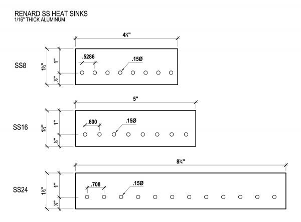
==Triac Heat Sink== | ==Triac Heat Sink== | ||
:A simple heat sink can be fabricated from | :A simple heat sink can be fabricated from flat aluminum (1/16” thick) available at your local home improvement store. The heat sinks most commonly included in the Kits and group buys are made in this fashion. You can use a different width flat bar if desired, '''''but you have to keep with the 1/16" thickness'''''. A template for the hole pattern can be found [[media:Renard SS24 heatsink template.pdf | here]]. The overall dimensions are shown [[media:Renard SS Heat Sink Pattern.jpg | here]]. '''The triac listed in the BOM has an isolated tab''', so no isolators are needed. | ||
| Line 194: | Line 198: | ||
{| border="1" cellpadding="10" style="text-align: center;" | {| border="1" cellpadding="10" style="text-align: center;" | ||
!width="200"| | !width="200"| PART NUMBER <br> (Mouser PN# unless noted) | ||
!width="50"| | !width="50"| QTY | ||
!width="100"| | !width="100"| REF | ||
!width="350" | !width="350"| NOMENCLATURE | ||
|- | |- | ||
|511-LF50CV ||1||U1 | |511-LF50CV ||1||U1 | ||
| Line 210: | Line 212: | ||
|align="left"|Optocoupler, Bi-Directional Input | |align="left"|Optocoupler, Bi-Directional Input | ||
|- | |- | ||
| | |815-ACH-18.432-EK||1||U3 | ||
|align="left"|Crystal Clock Oscillator, 18.432 MHz | |align="left"|Crystal Clock Oscillator, 18.432 MHz | ||
|- | |- | ||
| | |595-SN65LBC176P ||2||U4, U5 | ||
|align="left"|Differential Bus Transceivers | |align="left"|Differential Bus Transceivers | ||
|- | |- | ||
|571-1- | |571-1-2199298-2||2|| | ||
|align="left"|IC Socket, 8 pin (for U4 & U5) | |align="left"|IC Socket, 8 pin (for U4 & U5) | ||
|- | |- | ||
| Line 222: | Line 224: | ||
|align="left"|PIC Microcontroller | |align="left"|PIC Microcontroller | ||
|- | |- | ||
|571-1- | |571-1-2199298-3||3|| | ||
|align="left"|IC Socket, 14 pin (for U6-U8) | |align="left"|IC Socket, 14 pin (for U6-U8) | ||
|- | |- | ||
| Line 228: | Line 230: | ||
|align="left"|Optoisolator, Triac Driver | |align="left"|Optoisolator, Triac Driver | ||
|- | |- | ||
|571-1- | |571-1-2199298-1||25|| | ||
|align="left"|IC Socket, 6 pin (for U2, M1-M24) | |align="left"|IC Socket, 6 pin (for U2, M1-M24) | ||
|- | |- | ||
|511- | |511-BTA06-600CW||24||T1-T24 | ||
|align="left"|Triac, | |align="left"|Triac, 6A 600V | ||
|- | |- | ||
|291-750-RC||2||R1, R2 | |291-750-RC||2||R1, R2 | ||
| Line 252: | Line 254: | ||
|align="left"|Resistor, Carbon Film 180 ohms 1/4W 5% | |align="left"|Resistor, Carbon Film 180 ohms 1/4W 5% | ||
|- | |- | ||
| | |652-4606X-AP1-331LF ||1||RN1 | ||
|align="left"|Resistor Network, 6 pin, 330ohms 2% | |align="left"|Resistor Network, 6 pin, 330ohms 2% | ||
|- | |- | ||
| | |511-1N5817||4||D1-D4 | ||
|align="left"|Diode | |align="left"|Diode | ||
|- | |- | ||
| Line 264: | Line 266: | ||
|align="left"|Diode, Zener 4.3V .5W | |align="left"|Diode, Zener 4.3V .5W | ||
|- | |- | ||
|604- | |604-WP710A10IT||2||FE, OE | ||
|align="left"|LED, 3mm Red | |align="left"|LED, 3mm Red | ||
|- | |- | ||
|604- | |604-WP710A10GT||4||PWR, HB, ZC, SD | ||
|align="left"|LED, 3mm Green | |align="left"|LED, 3mm Green | ||
|- | |- | ||
|140- | |140-REA222M1CBK1320P||1||C1 | ||
|align="left"| Radial Electrolytic Capacitor 16V 2200uF 20% | |align="left"| Radial Electrolytic Capacitor 16V 2200uF 20% | ||
|- | |- | ||
|140- | |140-REA470M1CBK0511P||1||C2 | ||
|align="left"| Radial Electrolytic Capacitor 16V 47uF 20% | |align="left"| Radial Electrolytic Capacitor 16V 47uF 20% | ||
|- | |- | ||
| Line 294: | Line 296: | ||
|align="left"|Header, 2 Pin | |align="left"|Header, 2 Pin | ||
|- | |- | ||
| | |806-SX1100-B||3|| | ||
|align="left"|Shunt | |align="left"|Shunt | ||
|- | |- | ||
|504-GMA-10||2||F1, F2 | |504-BK/GMA-10-R||2||F1, F2 | ||
|align="left"|Fuse, Fast Acting 10A | |align="left"|Fuse, Fast Acting 10A | ||
|- | |- | ||
| Line 311: | Line 313: | ||
If you are planning on ordering from [http://www.mouser.com Mouser Electronics] you can use this [http://www.mouser.com/ProjectManager/ProjectDetail.aspx?AccessID=72eedcb487 Shared Project] to make it easier to order the parts. | |||
==Hardcopy Instructions== | |||
: [[media: Wiki - Renard SS24 Board Assembly.pdf | Click here for a pdf version of these instructions.]] | |||
: [[media: Wiki - Renard SS24 Board Assembly (doc file).zip | Click here for a doc version of these instructions that you can edit to rearrange the instructions to your personal preference.]] | |||
==Related Links== | ==Related Links== | ||
| Line 357: | Line 328: | ||
:[[Troubleshooting_Guide_The_Renard_SS24 | Troubleshooting Guide The Renard SS24]] | :[[Troubleshooting_Guide_The_Renard_SS24 | Troubleshooting Guide The Renard SS24]] | ||
:[http://doityourselfchristmas.com/forums/showthread.php?6664-The-Renard-SS-24-is-now-available!-(first-post-is-current-2-19-2011) Board Availability Information] | |||
:[[Renard Main Page]] | :[[Renard Main Page]] | ||
| Line 373: | Line 346: | ||
[[Category:Renard SS24]] | [[Category:Renard SS24]] | ||
[[Category:DIYC Index]] | |||
Latest revision as of 22:56, 28 December 2020
Board Assembly
- The following sequence of steps is by no means the only way to assemble the Renard SS24. It is simply a suggested order of events to achieve the desired goal.
- NOTE: The part numbers referenced in the following instructions are those taken from the Renard SS24 BOM.
|

|
|

|
|

|
|

|
|

|
|

|
|

|
|

|
|

|
|

|
|

|
| |
|

|
|

|
|

|
|

|
|

|
|

|
|

|
|

|
| |
|

|
|

|
|

|
|

|
|
|
|

|
|

|
|

|
|

|
| |
| |
|

|
|

|
|

|
|

|
|

|
|

|


Triac Heat Sink
- A simple heat sink can be fabricated from flat aluminum (1/16” thick) available at your local home improvement store. The heat sinks most commonly included in the Kits and group buys are made in this fashion. You can use a different width flat bar if desired, but you have to keep with the 1/16" thickness. A template for the hole pattern can be found here. The overall dimensions are shown here. The triac listed in the BOM has an isolated tab, so no isolators are needed.
- A small amount of heat transfer compound should be applied between the heat sink and the tab of the triacs. You can use the same compounds that are used on computer CPU chips and their heat sinks. If you don't have any available locally, you can always use something like Mouser PN# 532-249.
Parts Listing (BOM)
IMPORTANT BOM INFORMATION:
Mouser part numbers are listed (unless otherwise noted) as a means of simplifying the listing. Mouser is not the only place to get these parts, they are used as the reference since they tend to have all the parts needed to complete the project. However, the parts can be procured from any electronics parts source that you prefer.
In the event that any of the following parts are not in stock at Mouser when you decide to order them, you can check the Part Substitutions wiki page and see if there any suggestions for alternative parts.
| PART NUMBER (Mouser PN# unless noted) |
QTY | REF | NOMENCLATURE |
|---|---|---|---|
| 511-LF50CV | 1 | U1 | 5 VDC Voltage Regulator |
| 532-577102B00 | 1 | Heatsink for Voltage Regulator | |
| 782-H11AA1 | 1 | U2 | Optocoupler, Bi-Directional Input |
| 815-ACH-18.432-EK | 1 | U3 | Crystal Clock Oscillator, 18.432 MHz |
| 595-SN65LBC176P | 2 | U4, U5 | Differential Bus Transceivers |
| 571-1-2199298-2 | 2 | IC Socket, 8 pin (for U4 & U5) | |
| 579-PIC16F688-I/P | 3 | U6-U8 | PIC Microcontroller |
| 571-1-2199298-3 | 3 | IC Socket, 14 pin (for U6-U8) | |
| 859-MOC3023 | 24 | M1-M24 | Optoisolator, Triac Driver |
| 571-1-2199298-1 | 25 | IC Socket, 6 pin (for U2, M1-M24) | |
| 511-BTA06-600CW | 24 | T1-T24 | Triac, 6A 600V |
| 291-750-RC | 2 | R1, R2 | Resistor, Carbon Film 750 ohms 1/4W 5% |
| 291-120-RC | 1 | R3 | Resistor, Carbon Film 120 ohms 1/4W 5% |
| 299-1K-RC | 2 | R4, R7 | Resistor, Carbon Film 1K ohms 1/8W 5% |
| 299-27K-RC | 3 | R5, R8, R9 | Resistor, Carbon Film 27K ohms 1/8W 5% |
| 299-680-RC | 25 | R6, R10-R33 | Resistor, Carbon Film 680 ohms 1/8W 5% |
| 291-180-RC | 24 | R34-R57 | Resistor, Carbon Film 180 ohms 1/4W 5% |
| 652-4606X-AP1-331LF | 1 | RN1 | Resistor Network, 6 pin, 330ohms 2% |
| 511-1N5817 | 4 | D1-D4 | Diode |
| 78-1N5239B | 1 | D6 | Diode, Zener 9.1V .5W |
| 78-1N5229B | 1 | D5 | Diode, Zener 4.3V .5W |
| 604-WP710A10IT | 2 | FE, OE | LED, 3mm Red |
| 604-WP710A10GT | 4 | PWR, HB, ZC, SD | LED, 3mm Green |
| 140-REA222M1CBK1320P | 1 | C1 | Radial Electrolytic Capacitor 16V 2200uF 20% |
| 140-REA470M1CBK0511P | 1 | C2 | Radial Electrolytic Capacitor 16V 47uF 20% |
| 80-C322C104K5R | 3 | C3-C5 | Capacitor, Radial Ceramic 50V 0.1uF |
| 571-2828372 | 24 | Channel Terminals | Terminal Block, 2 Pos 5.08 mm |
| 571-7969492 | 2 | Power Terminals | Terminal Block, 2 Pos 5.08 mm |
| 152-3409 | 1 | JDP1 | D-Sub Connectors, Right Angle DE9 |
| 571-5556416-1 | 2 | J1, J2 | Jack, Modular RJ45 PCB Mount Top Entry |
| 538-22-03-2021 | 3 | JP1-JP3 | Header, 2 Pin |
| 806-SX1100-B | 3 | Shunt | |
| 504-BK/GMA-10-R | 2 | F1, F2 | Fuse, Fast Acting 10A |
| 534-3517 | 4 | Holder, Fuse Clip PCB mount 5mm | |
| 534-3527C | 2 | Cover, Fuse | |
| 838-3FS-312 | 1 | TF1 | Power Transformers 12.6VCT@.2A 6.3V@.4A Single Primary |
If you are planning on ordering from Mouser Electronics you can use this Shared Project to make it easier to order the parts.
Hardcopy Instructions