Ren-T PCB Assembly Instructions
Board Assembly
Assembling the Ren-T should be fairly easy for most hobbyists. There are three different ways the Ren-T PCB can be populated and should be considered before building the board. You can build the board with all the parts without any negative impact on the board operation.
The following procedures were done with a V2.4 version of the Ren-T PCB. The V2.5 version of the board eliminated some unnecessary parts that were causing confusion. These procedures are geared towards the Case #3 build option which is the most commonly used configuration.
The following sequence of steps is by no means the only way to do this. It is simply a suggested order of events to achieve the desired goal.
- Start by checking the PCB over for any production faults. Ensure that none of the tracks are shorted or open and that all holes are clear.

- Due to differences in the transformers that are capable of being used on the Ren-T, there are no mounting holes provided for the transformer. Temporarily place the transformer in its mounting position, placing the transformer leads in the correct pads will ensure you have the transformer correctly mounted. Mark the position for the mounting hardware. Remove the transformer from the PCB. Drill the holes needed for the mounting hardware.

- Install resistor R1 (PN# 291-1K-RC). Make sure that the resistor has a value of 1Kohms (brown/black/red/gold stripes). The resistor has no polarity to worry about.
- Install resistor R2 (PN# 291-750-RC). Make sure that the resistor has a value of 750ohms (violet/green/brown/gold stripes). The resistor has no polarity to worry about.
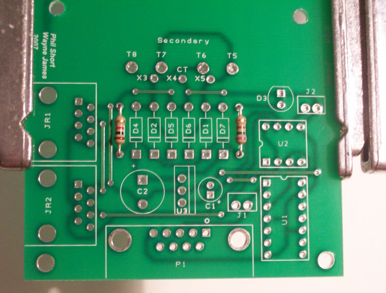

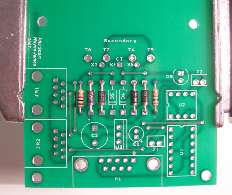
- Install the four diodes D1, D2, D4, D7 (PN# 625-1N5819-E3). The diodes must go in correctly. Each diode should/will have a silver/white stripe on one end of the diode body. Make sure that this stripe lines up with the stripe on the silk screen mask on the PCB.
- Diodes D5 & D6 are not used and were eliminated from the V2.5 PCB.

- Install capacitor C1 (PN# 140-XRL16V10-RC). This capacitor is polarized and must be mounted correctly. The capacitor should have a black stripe on the body to indicate which lead is negative. The positive lead of the capacitor will be the longer lead. Make sure that the positive lead is placed in the square solder pad.
- Install voltage regulator U3 (PN# 595-UA78L05ACLPRE3). This device must also be correctly mounted. Make sure that the flat side of U3 is aligned with the silk screen. If unsure, then make sure that the flat side is toward capacitor C1 that you just installed.
- Install capacitor C2 (PN# 140-XRL16V470-RC). This capacitor is polarized and must be mounted correctly. The capacitor should have a black stripe on the body to indicate which lead is negative. The positive lead of the capacitor will be the longer lead. Make sure that the positive lead is placed in the square solder pad.

- Install power LED D3 (PN# 604-WP7104GT [Green color] or 604-WP7104IT [Red color]). The LED is polarized and must be mounted correctly. The short lead is the cathode and must be placed in the square solder pad. Another way to check is if your LED has a flat side to it then that side must be aligned with the silk screen.
The next two items are optional but if you are going to use them then now would be a good time to install them.
- Install the 14 pin IC socket (PN# 571-3902613).
- Install the 8 pin IC socket (PN# 571-3902612).
- Pin 1 of the sockets must be aligned with the square solder pad. Another way to verify that you installed them correctly is to make sure that the notch on the socket is aligned with the notch on the PCB silk screen outline.

- Install the RJ45 jack socket JR1 (PN# 571-5520251-4). Due to minor variations in manufacturing, some RJ45 sockets are a tighter fit than others. Care should be taken to ensure that the pins are aligned first before applying too much pressure to seat the locking lugs through the board.
- Install the DB9 connector P1 (PN# 152-3409). Ensure all the pins are through the PCB before applying too much pressure to seat the locking lugs.

- Install the AC power entry module (PN# 693-CMF1.1111.12), if desired.
- Install the transformer (recommended part is PN# 41PG300). Care must be exercised at this step on the V2.4 PCB since there are multiple holes on the PCB for the transformer leads. On the primary side of the transformer the leads go to the holes marked X1 and X2. On the secondary side of the transformer the leads go to the holes marked X3, X4(CT) and X5. The leads should come straight down from the transformers body into the holes. The leads should not be crossed or making contact with anything other than the hole. Install the transformer mounting hardware when the transformer is correctly positioned.

- Install IC U1 (PN# 595-SN75C189AN) into the 14 pin IC socket. Ensure that pin 1 of the IC is aligned with pin 1 of the socket. Can be verified by noting that the notch on the IC is aligned with the notch on the socket.
- Install IC U2 (PN# 837-ISL81487EIP) into the 8 pin IC socket. Ensure that pin 1 of the IC is aligned with pin 1 of the socket. Can be verified by noting that the notch on the IC is aligned with the notch on the socket.

CONGATULATIONS! You have just finished building your Ren-T board.
- Some other views of your completed Ren-T


BOM
- 1 - 41PG300 - 12.6V Center-Tap Transformer
- U3 ~ 1 - 595-UA78L05ACLPRE3 - Standard 5V, 100mA Fixed Pos Voltage Regulator
- U2 ~ 1 - 837-ISL81487EIP - RS-485/422 Interface ICs 5V TXRX ESD
- U1 ~ 1 - 595-SN75C189AN - RS-232 Interface ICs Quad Low Pwr
- C1 ~ 1 - 140-XRL16V10-RC - Radial Electrolytic Capacitors 16V 10uF 20%
- C2 ~ 1 - 140-XRL16V470-RC - Radial Electrolytic Capacitors 10V 470uF 20%
- D1, D2, D4, D7 ~ 4 - 625-1N5819-E3 - Schottky Rectifiers Vr/40V Io/1A
- D3 ~ 1 - 604-WP7104GT ***(or)*** 604-WP7104IT - LED > GT = Green ~ IT = Red
- R1 ~ 1 - 291-1K-RC - 1/4W 5% Carbon Film Resistors 1Kohms 0.05
- R2 ~ 1 - 291-750-RC - 1/4W 5% Carbon Film Resistors 750ohms 0.05 (LED resistor)
- J1, J2 ~ 2 - 538-22-03-2021 - .100 K.K. Connectors VERT PCB HDR 2P TIN PLATING
- 2 - 649-65474-002LF - Bergcon Connectors SHUNT TIN
- P1 ~ 1 - 152-3409 - D-Sub Connectors 9C R/A PCB RECPT
- JR1, JR2 ~ 2 - 571-5520251-4 - Modular Jacks 8/8 SIDE ENTRY
Optional Parts
- 1 - 693-CMF1.1111.12 - Power Entry Modules 2.5A C8 INLET PCB MT (requires the AC cord below, or an older style 'laptop' power cord. Check the data sheet for a picture.)
- 1 - 173-21114-E - AC Power Cord 10' 2W 18AWG BK
- 1 - 571-3902613 - IC Sockets 14P ECONOMY TIN
- 1 - 571-3902612 - IC Sockets 8P ECONOMY TIN