Renard-595 Converter: Difference between revisions
| (16 intermediate revisions by 5 users not shown) | |||
| Line 1: | Line 1: | ||
== Introduction == | == Introduction == | ||
The Renard-595 Converter (aka Ren-C) board is designed to allow the 64-Channel Olsen 595 and GRINCH controller boards to be controlled through the serial port of a PC. The Ren-C also adds a 192-level dimming capability to these boards. | |||
The current 595-style (including the GRINCH) controllers are designed to turn display lights on and off under computer control. They are connected to the parallel port of the controlling PC and have the capability of being daisy-chained together. This daisy-chain configuration allows up to approximately 1024 channels to be controlled through one parallel port. This large channel count is highly desirable by many users but the lack of a dimming capability frustrates many others. Previous attempts to add a dimming capability to these systems resulted in using eight on/off channels to create one channel with dimming capability. The complexity of the design and cost in resources kept it from being widely used, thus the need for a different solution and the birth of the Ren-C. | |||
<br> | |||
==The Board== | |||
[[Image:Ren-C (top).jpg]] | |||
<br> | |||
[[Image:Ren-C (dwg).jpg]] | |||
<br> | |||
==Circuit Diagram== | |||
The schematic diagram can be found [http://www.doityourselfchristmas.com/wiki/images/e/ec/Protel_Schematic_V2.0.2.pdf here]. | |||
The PCB diagram can be found [http://www.doityourselfchristmas.com/wiki/images/f/fb/Multilayer_Composite_Print_V2.0.2.pdf here]. | |||
The | |||
'''Connectors''' | |||
:* '''To 595 In (JP1)''' – Provides the Data, Clock and Strobe signals to the 595/GRINCH controller. Also, provides the Ren-C an operating voltage from the 595/GRINCH controller. | |||
:* '''From 595 Out (JP2)''' – Brings the output of the shift-register on the 595/GRINCH board back to the Ren-C to enable PWM operation. This cable can be omitted if PWM operation is not needed/desired. | |||
:* '''RS IN (JP4)''' – RS232/RS485 incoming data and ZC signals from an up-stream controller board or controlling PC. | |||
:* '''RS OUT (JP5)''' – RS232/RS485 outgoing data and ZC signals for downstream controller boards. | |||
'''IC Chips''' | |||
:* '''U1''' – RS232/RS485 Receiver/Transmitter | |||
:* '''U2''' – Quad NOR gate | |||
:* '''U3''' – PIC16F627A Microcontroller (the brain of the Ren-C) | |||
'''Diagnostic LEDs''' | |||
:* '''D3''' Heartbeat – Blinks on/off at the rate of the ZC signal | |||
:* '''D4''' Overrun – Indicates an data overrun error in the usart of the PIC | |||
:* '''D5''' Framing – Indicates a data framing error in the usart of the PIC | |||
:* '''D6''' Power – Lit whenever power is applied to the board | |||
:* '''D7''' Rx – Lit whenever RS232/RS485 data is received by the PIC | |||
'''Headers''' | |||
:* '''JP3''' – 4-pin connector that provides an alternate method for bringing the ZC signal and operating voltage (5 VDC) onto the board. | |||
:* '''JP6''' - 6-pin connector that can be used to program the PIC in-circuit with either a PicKit2 Programmer (DV164120 or PG164120) or the bare programmer from PicKit1 (PG164101). | |||
'''Test Points''' | |||
:* '''TP1''' – Clock Out | |||
:* '''TP2, TP5''' – PWM Reset In | |||
:* '''TP3''' – Data Out | |||
:* '''TP4''' – Strobe Out | |||
==Firmware== | |||
:The PIC (U3) must be programmed with the latest firmware for the Ren-C to operate properly. The firmware can be found [[Renard Firmware#Firmware for Ren-C | here]]. | |||
==Connection== | |||
:Some of the signals on the Ren-C are fairly high-speed (2.5 MHz), so the cables between the Ren-C board and the 595/GRINCH controller should be as short as possible. Cable length should not exceed 6". | |||
'''Typical Single Ren-C Connection''' | |||
[[Image: Ren-C Layout 1.jpg |800px]] <br> | |||
'''Typical Multiple Ren-C Connection''' | |||
[[Image: Ren-C Layout 2.jpg |800px]] <br> | |||
'''Other Connections''' | |||
:*The Ren-C/GRINCH(Olsen 595) combo can be worked into any display configuration with other Renard based controller boards on the same serial port connection. The main requirement is that the Ren-C/GRINCH(Olsen 595) combo must receive valid Renard protocol formatted channel data and a ZC signal. | |||
''' | '''Limitations''' | ||
:*The number of Ren-C/GRINCH(Olsen 595) combos that can be linked together is limited by the maximum amount of channels that can be achieved based on the baud rate and event interval that VIXEN is using. More information on this limitation can be found [[Renard#Number of Circuits (Channels)| here]]. | |||
'''ZC''' | ==Powering the Ren-C== | ||
The Ren-C requires an external power source to operate. This power source must be regulated/filtered 5 VDC. There are two possible methods of applying power to the Ren-C. | |||
'''Power Connections''' | |||
:*'''Option 1''' [Preferred Method] | |||
:::The Ren-C can get it’s operating voltage from the COOP OLSEN 595 or GRINCH controller board that it is connected to. With this option the COOP OLSEN 595 or GRINCH controller board would be connected directly to the external 5 VDC power supply at either P1 or J2 respectfully. By placing a shunt on J1, this would allow the 5 VDC to be passed to the Ren-C via the RJ45 IN/OUT connectors on pin 1. | |||
:*'''Option 2''' | |||
:::The Ren-C can be powered directly by an external 5 VDC power supply. This can be accomplished by connecting 5VDC to pin 4 and GND to pin 1 of header JP3. When using this option you should remove the shunt from J1 of the connected COOP OLSEN 595 or GRINCH controller board to prevent any problems with the associated external power sources. | |||
There are many options of what to use for the external power source. Some users prefer to use an unused hard drive power connection inside the computer that is being used to run VIXEN. Others prefer to use an old computer power supply that they modify to run as a stand-alone power supply. And there are others that have had success in using wall-warts but care should be used with wall-warts since not all of them provide a regulated/filtered output. | |||
==Zero Crossing Signal Options== | |||
The Zero Crossing (ZC) signal is one of the most difficult signals for new users to understand. Simply put, ZC is the point at which the AC signal crosses zero volts. The ZC point needs to be known so that the triacs can be turned on/off at the correct time to achieve a dimming effect. | |||
One of the factors that adds to confusion is that the ZC signal is actually different at various points in the overall light control process. The output of the Ren-T (green trace in picture below) is commonly referred to as a ZC signal. This raw ZC is not in a suitable form to be used by the PIC. By applying this signal to base of Q1 on the Ren-C, we will get a new ZC signal (purple trace in picture below) that the PIC can use to for the dimming timing. | |||
Now that you understand the ZC signal, you can better decide how you want to get a ZC signal on the Ren-C. | |||
:*'''Option 1''' | |||
:::ZC can be generated on the board, by connecting a 9VDC (unregulated and unfiltered) supply to pins #7,8 of the RS IN RJ45 socket. This input signal (green trace in picture below) is a pulsating signal, rising from 0V to 9V and back in time with the AC power line (100 or 120 times per second, depending on your locale). This signal is the normal output from the Ren-T or it can be created using this [[Renard Connection Instructions#Ren-T (Transformer Board)|circuit]]. | |||
:*'''Option 2''' | |||
:::ZC can be generated on the board, by connecting a 9VDC (unregulated and unfiltered) supply to The "ZC In" pin (#3) of JP3. This signal (green trace in picture below) can be created using a schematic like this [[Renard Connection Instructions#Ren-T (Transformer Board)|circuit]]. With this option, you will need to install a 10K resistor in location R1 instead of R9. | |||
:*'''Option 3''' | |||
:::ZC can be connected directly to the board, by connecting a ZC Signal (purple trace in picture below), to the "ZC" pin (#2) of JP3. With this option, you can remove R1, R9 and Q1. | |||
[[Image:ZeroCross.gif|center]] | |||
==ZC and RENT requirements== | |||
When the REN64XB and RENC were first released, there was an extra board that was made available, the RENT. The function of the RENT was to provide power and a source of ZC to the controllers. | |||
The RENC did not require separate power as it draws 5 V DC from the GRINCH board. What it does need is a source of ZC. | |||
What is ZC? Zero Cross reference. When dimming, the RENC needs to know the start of the AC signal waveform, i.e. when it crosses over Zero V AC. A small sample of AC voltage is required to obtain the ZC. | |||
There are a couple of options. | |||
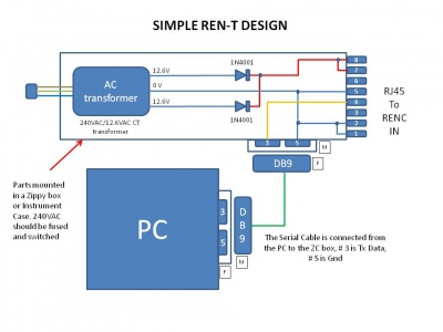
Option 1 - User a small AC stepdown transformer (12.6V CT) and build a simple circuit to rectify the Low V AC to DC. | |||
[[Image:Simple RenT Design.jpg | 400px]] | |||
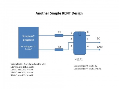
Option 2 - Use a small AC stepdown transformer (12.6V CT) and build a OPTOISOLATOR circuit to provide a source of ZC. | |||
NOTE - the diagram should have an H11AA1, not an H11A1 in this circuit. | |||
[[Image:Another RENT (H11A1).jpg | 400px]] | |||
==Computer Setup== | |||
'''VIXEN Settings''' | |||
:*The Ren-C requires the Renard Dimmer or Renard Dimmer (modified) Plug-In. | |||
::'''Renard Dimmer Plug-In Settings:''' | |||
:::Protocol Version: 1 | |||
:::COM1 (or whichever COM port you are connected to) | |||
:::Baud: 57600 | |||
:::Parity: None | |||
:::Data bits: 8 | |||
:::Stop bits: One | |||
==Related Links== | |||
[[REN-C_PCB_ASSEMBLY_INSTRUCTIONS | Ren-C PCB Assembly Instructions]] <br /> | |||
[[The_GRINCH_Controller | The GRINCH Controller]] <br /> | |||
[[64 Channel Olsen 595 Controller Assembly Instructions | COOP OLSEN 595 Controller]] <br /> | |||
[[Ren-T_Assembly_Instructions|REN-T]]<br /> | |||
[[Vixen|VIXEN]]<br /> | |||
[[Category:Ren-C]] | |||
[[Category:Renard]] | |||
[[Category:The Grinch]] | |||
[[Category:Olsen 595]] | |||
[[Category:DIYC Index]] | |||
Latest revision as of 02:02, 19 February 2012
Introduction
The Renard-595 Converter (aka Ren-C) board is designed to allow the 64-Channel Olsen 595 and GRINCH controller boards to be controlled through the serial port of a PC. The Ren-C also adds a 192-level dimming capability to these boards.
The current 595-style (including the GRINCH) controllers are designed to turn display lights on and off under computer control. They are connected to the parallel port of the controlling PC and have the capability of being daisy-chained together. This daisy-chain configuration allows up to approximately 1024 channels to be controlled through one parallel port. This large channel count is highly desirable by many users but the lack of a dimming capability frustrates many others. Previous attempts to add a dimming capability to these systems resulted in using eight on/off channels to create one channel with dimming capability. The complexity of the design and cost in resources kept it from being widely used, thus the need for a different solution and the birth of the Ren-C.
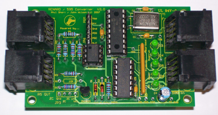
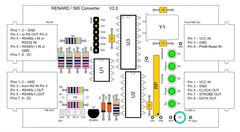
The Board
Circuit Diagram
The schematic diagram can be found here.
The PCB diagram can be found here.
Connectors
- To 595 In (JP1) – Provides the Data, Clock and Strobe signals to the 595/GRINCH controller. Also, provides the Ren-C an operating voltage from the 595/GRINCH controller.
- From 595 Out (JP2) – Brings the output of the shift-register on the 595/GRINCH board back to the Ren-C to enable PWM operation. This cable can be omitted if PWM operation is not needed/desired.
- RS IN (JP4) – RS232/RS485 incoming data and ZC signals from an up-stream controller board or controlling PC.
- RS OUT (JP5) – RS232/RS485 outgoing data and ZC signals for downstream controller boards.
IC Chips
- U1 – RS232/RS485 Receiver/Transmitter
- U2 – Quad NOR gate
- U3 – PIC16F627A Microcontroller (the brain of the Ren-C)
Diagnostic LEDs
- D3 Heartbeat – Blinks on/off at the rate of the ZC signal
- D4 Overrun – Indicates an data overrun error in the usart of the PIC
- D5 Framing – Indicates a data framing error in the usart of the PIC
- D6 Power – Lit whenever power is applied to the board
- D7 Rx – Lit whenever RS232/RS485 data is received by the PIC
Headers
- JP3 – 4-pin connector that provides an alternate method for bringing the ZC signal and operating voltage (5 VDC) onto the board.
- JP6 - 6-pin connector that can be used to program the PIC in-circuit with either a PicKit2 Programmer (DV164120 or PG164120) or the bare programmer from PicKit1 (PG164101).
Test Points
- TP1 – Clock Out
- TP2, TP5 – PWM Reset In
- TP3 – Data Out
- TP4 – Strobe Out
Firmware
- The PIC (U3) must be programmed with the latest firmware for the Ren-C to operate properly. The firmware can be found here.
Connection
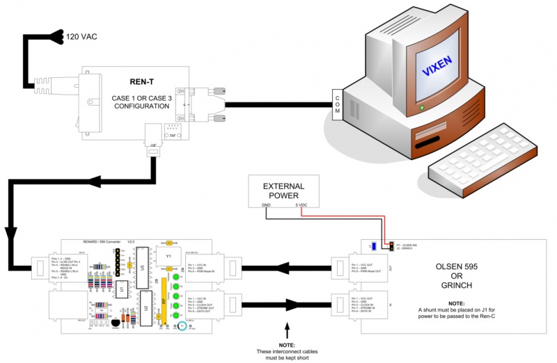
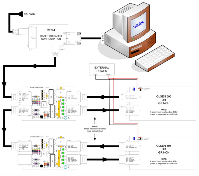
- Some of the signals on the Ren-C are fairly high-speed (2.5 MHz), so the cables between the Ren-C board and the 595/GRINCH controller should be as short as possible. Cable length should not exceed 6".
Typical Single Ren-C Connection
Typical Multiple Ren-C Connection
Other Connections
- The Ren-C/GRINCH(Olsen 595) combo can be worked into any display configuration with other Renard based controller boards on the same serial port connection. The main requirement is that the Ren-C/GRINCH(Olsen 595) combo must receive valid Renard protocol formatted channel data and a ZC signal.
Limitations
- The number of Ren-C/GRINCH(Olsen 595) combos that can be linked together is limited by the maximum amount of channels that can be achieved based on the baud rate and event interval that VIXEN is using. More information on this limitation can be found here.
Powering the Ren-C
The Ren-C requires an external power source to operate. This power source must be regulated/filtered 5 VDC. There are two possible methods of applying power to the Ren-C.
Power Connections
- Option 1 [Preferred Method]
- The Ren-C can get it’s operating voltage from the COOP OLSEN 595 or GRINCH controller board that it is connected to. With this option the COOP OLSEN 595 or GRINCH controller board would be connected directly to the external 5 VDC power supply at either P1 or J2 respectfully. By placing a shunt on J1, this would allow the 5 VDC to be passed to the Ren-C via the RJ45 IN/OUT connectors on pin 1.
- Option 2
- The Ren-C can be powered directly by an external 5 VDC power supply. This can be accomplished by connecting 5VDC to pin 4 and GND to pin 1 of header JP3. When using this option you should remove the shunt from J1 of the connected COOP OLSEN 595 or GRINCH controller board to prevent any problems with the associated external power sources.
There are many options of what to use for the external power source. Some users prefer to use an unused hard drive power connection inside the computer that is being used to run VIXEN. Others prefer to use an old computer power supply that they modify to run as a stand-alone power supply. And there are others that have had success in using wall-warts but care should be used with wall-warts since not all of them provide a regulated/filtered output.
Zero Crossing Signal Options
The Zero Crossing (ZC) signal is one of the most difficult signals for new users to understand. Simply put, ZC is the point at which the AC signal crosses zero volts. The ZC point needs to be known so that the triacs can be turned on/off at the correct time to achieve a dimming effect.
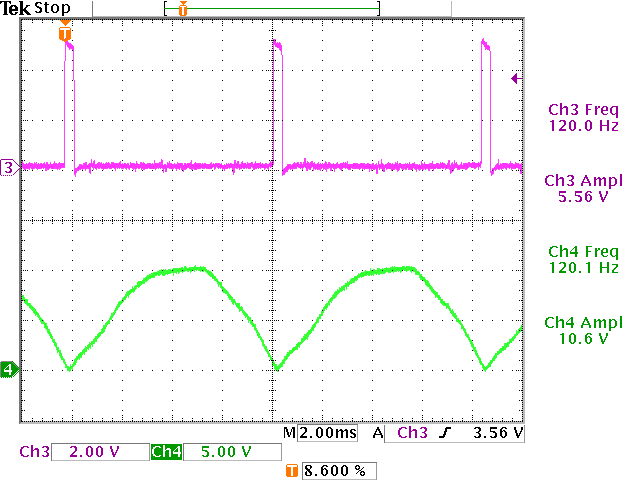
One of the factors that adds to confusion is that the ZC signal is actually different at various points in the overall light control process. The output of the Ren-T (green trace in picture below) is commonly referred to as a ZC signal. This raw ZC is not in a suitable form to be used by the PIC. By applying this signal to base of Q1 on the Ren-C, we will get a new ZC signal (purple trace in picture below) that the PIC can use to for the dimming timing.
Now that you understand the ZC signal, you can better decide how you want to get a ZC signal on the Ren-C.
- Option 1
- ZC can be generated on the board, by connecting a 9VDC (unregulated and unfiltered) supply to pins #7,8 of the RS IN RJ45 socket. This input signal (green trace in picture below) is a pulsating signal, rising from 0V to 9V and back in time with the AC power line (100 or 120 times per second, depending on your locale). This signal is the normal output from the Ren-T or it can be created using this circuit.
- Option 2
- ZC can be generated on the board, by connecting a 9VDC (unregulated and unfiltered) supply to The "ZC In" pin (#3) of JP3. This signal (green trace in picture below) can be created using a schematic like this circuit. With this option, you will need to install a 10K resistor in location R1 instead of R9.
- Option 3
- ZC can be connected directly to the board, by connecting a ZC Signal (purple trace in picture below), to the "ZC" pin (#2) of JP3. With this option, you can remove R1, R9 and Q1.
ZC and RENT requirements
When the REN64XB and RENC were first released, there was an extra board that was made available, the RENT. The function of the RENT was to provide power and a source of ZC to the controllers.
The RENC did not require separate power as it draws 5 V DC from the GRINCH board. What it does need is a source of ZC.
What is ZC? Zero Cross reference. When dimming, the RENC needs to know the start of the AC signal waveform, i.e. when it crosses over Zero V AC. A small sample of AC voltage is required to obtain the ZC.
There are a couple of options.
Option 1 - User a small AC stepdown transformer (12.6V CT) and build a simple circuit to rectify the Low V AC to DC.
Option 2 - Use a small AC stepdown transformer (12.6V CT) and build a OPTOISOLATOR circuit to provide a source of ZC. NOTE - the diagram should have an H11AA1, not an H11A1 in this circuit.
Computer Setup
VIXEN Settings
- The Ren-C requires the Renard Dimmer or Renard Dimmer (modified) Plug-In.
- Renard Dimmer Plug-In Settings:
- Protocol Version: 1
- COM1 (or whichever COM port you are connected to)
- Baud: 57600
- Parity: None
- Data bits: 8
- Stop bits: One
Related Links
Ren-C PCB Assembly Instructions
The GRINCH Controller
COOP OLSEN 595 Controller
REN-T
VIXEN
