10W RGB LED Driver Board and BOM Group Buy, ROUND 2

That's what was in my head,but I highlighted the wrong piece. Make it look like the opposite side basically.

No, you'll remove the piece just to the right of the tabs you highlighted - the section with the hole in it that connects all three tabs. You'll need to clip all three tabs to remove it and leave the tabs you highlighted to solder to the board.
 
Any problem in changing the installation order by installing the leds after the diodes but before the taller capacitor, transistors ect...

Having assembled several, there should be no problem doing them in this order. If you do the LEDs earlier in the process, you'll want to be gentle with them as you assemble the other items.
 
Soldered all of mine up. Of the ten, five worked immediately, 4 more worked after a solder touch up of either an IC or a diode. Number ten is not working at all. When I apply power just like the other nine, R1,R2, R3 get very hot. I have inspected all parts for orientation and have reflowed the board, no bridges or shorts that I can see. Everything "Looks ok", any suggestions?
 
Did you check to see if the 5V regulator is putting out +5V?
I'm thinking it is not the IC's if all 3 resistors are getting hot.
You may also need to check the LED independently.
Can you give it 3-5V with an inline resistor directly to see if it lights. It wouldn't be the first LED i've bought where the anode and cathode are reversed.
Soldered all of mine up. Of the ten, five worked immediately, 4 more worked after a solder touch up of either an IC or a diode. Number ten is not working at all. When I apply power just like the other nine, R1,R2, R3 get very hot. I have inspected all parts for orientation and have reflowed the board, no bridges or shorts that I can see. Everything "Looks ok", any suggestions?
 
We have ordered some prototype Renard to Flood adapter boards.
Three adapters on each panel. They will need to be cut apart.
They take in 3 Cat5 cables (4 channels) and fan them out to 4 Cat5 cables to 4 Floods.
They have power injection to the Floods. The power injection has the option of a 3 amp diode in case of reverse power connections.
There is also a jumper to attach the pin 7 ground as a return to REN32/64.
Expect to see them in about 3 weeks.
Here's what they look like.
Click to enlarge:
3d top.jpg
3d bottom.jpg
 
Last edited:
Good to hear. Will they be small enough to maybe put in side the 10w flood housing? or are there another solution?

We have ordered some prototype Renard to Flood adapter boards.
Three adapters on each panel. They will need to be cut apart.
They take in 3 Cat5 cables (4 channels) and fan them out to 4 Cat5 cables to 4 Floods.
They have power injection to the Floods. The power injection has the option of a 3 amp diode in case of reverse power connections.
There is also a jumper to attach the pin 7 ground as a return to REN32/64.
Expect to see them in about 3 weeks.
Here's what they look like.
Click to enlarge:
View attachment 27499
View attachment 27500
 
Last edited:
As soon as I get my solder paste,I'm going to assemble them. How do I go about testing them?
 
Wouldn't we be better off putting the breakout board with the Ren 48lsd? Of course you can put it at either end or even in the middle. But you need to run 3 cat5 wires from the Ren 48lsd to the breakout board and one cat5 from the breakout board to each of 4 floods. If you put it with a flood you need the 3 cat5 from the Ren 48lsd to it and 3 cat5 leaving it to other floods.
 
Exactly correct !

Also, with the REN32/64, you also have to provide room for a power supply for the power injection.

So, it's going to vary a lot based on how you want to setup your show.
Wouldn't we be better off putting the breakout board with the Ren 48lsd? Of course you can put it at either end or even in the middle. But you need to run 3 cat5 wires from the Ren 48lsd to the breakout board and one cat5 from the breakout board to each of 4 floods. If you put it with a flood you need the 3 cat5 from the Ren 48lsd to it and 3 cat5 leaving it to other floods.
 
Will there be a GB #3 ?

I would like to get another 50 of these for solid color 10w leds .

The 10w rgb for blue is not as good as it could be .

The down side to the rgb led is that only 3 of the 9 in the array are used opposed to the solid colors using all 9 .

Thanks in advance .
 
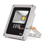
Has anyone used this style of housing fixture with this driver board?
Will it work? I was hopping to use a Komby RF1 behind the glass front.
attachment.php
 

Attachments

  • flood large front.jpg
    flood large front.jpg
    48.7 KB · Views: 123
I have one of those on my work bench at home. I'll try an RF_1 in it when I get home tonight. If it fits I'll be pissed... I bought 10 of the old style.
Doug

Sent from my SPH-D710 using Tapatalk
 
Last edited:
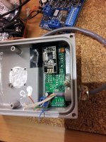
Looks like it will barely fit. I don't have an assembled RF_1 here. They are all in storage. This is a PCB that I started to assemble and I've placed the radio on it so you can see how it fits. The problem I see is that your transmitter will have to be in front of the flood or the metal housing will block the signal.
 

Attachments

  • 10wSmallFlood.jpg
    10wSmallFlood.jpg
    128.7 KB · Views: 57
I wonder if it makes sense to fish and external antenna out of these units?
Anyone tried doing that with these modules?
Looks like it will barely fit. I don't have an assembled RF_1 here. They are all in storage. This is a PCB that I started to assemble and I've placed the radio on it so you can see how it fits. The problem I see is that your transmitter will have to be in front of the flood or the metal housing will block the signal.
 
Back
Top