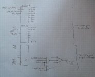
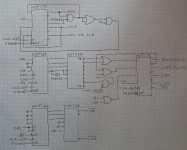
Having been put off by discovering the pointlessness of my 'alternative controller' design, I thought that I'd do another pointless design. This one uses only a Wemos (or other controller with a fast SPI slave port) and old-school TTL/CMOS logic. This design would be good for up to about 6000+ WS2811-type pixels, and the only assumption that it makes is that 8266 SPI port is good for slave mode at 8 Mbps. One proviso, though, is that software might need to rearrange the output bytes - this design assumes that the data for the 8 output ports is in port-order first.
You are using an out of date browser. It may not display this or other websites correctly.
You should upgrade or use an alternative browser.
You should upgrade or use an alternative browser.
Alternative TTL Logic Pixel Controller
- Thread starter P. Short
- Start date
MartinMueller2003
Supporting Member
Look at the ESPixelStick code for the WS2801 code.
dirknerkle
Supporting Member
Phil, don't be put off by the supposed "pointlessness" of your alternate controller design. Every design has usefulness, especially in light of the increasing difficulties in securing various chips and other parts. Keep going!
Phil, don't be put off by the supposed "pointlessness" of your alternate controller design. Every design has usefulness, especially in light of the increasing difficulties in securing various chips and other parts. Keep going!
Thank you for your kind comment. This one is more of an exercise in going against the grain and doing it my way than anything else.
Thank you for your kind comment. This one is more of an exercise in going against the grain and doing it my way than anything else.
That statement right there is the epitome of fun in experimenting in this hobby .
onword->
")
MartinMueller2003
Supporting Member
The WS2801 driver is one of the SPI based outputs supported by V4. There are a few gotchas when using the SPI interface, like the interrupts do not allow you to properly feed the hardware engine etc. I had to add a background task to feed the engine at an appropriate task level.Hey, let's be cryptic. What would I be looking for? SPI running with an 8MHz clock in slave mode? Or evidence that I'm wasting my time? or something else all together?
The WS2801 driver is one of the SPI based outputs supported by V4. There are a few gotchas when using the SPI interface, like the interrupts do not allow you to properly feed the hardware engine etc. I had to add a background task to feed the engine at an appropriate task level.
Thanks. The part about disabling interrupts is totally expected, the hardware engine that I'm working with depends on a continuous data feed without any breaks.
Where is the SPI clock coming from when it's operating in slave mode? I'm suspecting that it comes from a PWM output that is fed back around to the SPI clock input. The SPI clock in the design that I'm playing with is derived from an external crystal oscillator, so I'm just a little bit worried about how well the SPI implementation deals with an SPI clock that is asynchronous with respect to it's internal clock.
MartinMueller2003
Supporting Member
i used the internal clock. it is pretty accurate
i used the internal clock. it is pretty accurate
I wish that I could do that, it would make things a bit easier.
MartinMueller2003
Supporting Member
If I remember correctly you can map the output of a timer to a pin. If you do a proper divider you would get the clock you are looking for.