You are using an out of date browser. It may not display this or other websites correctly.
You should upgrade or use an alternative browser.
You should upgrade or use an alternative browser.
dc ssr dc troubleshooting
- Thread starter daytimer
- Start date
g2ktcf
New member
I too have the same problem. Discoverd it last night after buying 100 mosfets. I purchased the rfd14n05l fet not awre that the pinout on the fet is different to the board.
I now have 48 boards with that are usless without modification. Frustrated.
Brett,
Where did you get the PN to order? I am trying to track down what is going on here as these are the ones I am going to be stocking in my online store.
Chris
g2ktcf
New member
Brett,
Where did you get the PN to order? I am trying to track down what is going on here as these are the ones I am going to be stocking in my online store.
Chris
Also, do not modify the board just yet as John says this is the wrong part......
EasyGo
New member
http://www.doityourselfchristmas.com/wiki/index.php?title=4_Channel_DCSSR_Assembly_Instructions#PCB_Overlay_Version_1.2
Even though the part in the Wiki is RFDxxx and the link RFPxxx, they should interchange for most purposes as the pinouts are the same (G-D-S). The RFDxxx is in a smaller TO-251 case where the RFPxxx is a TO-220 case.
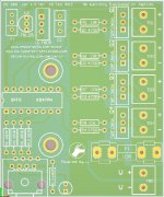
None of these parts is going to work without modifications on the board pictured in daytimer's post.
The original MOSFET used was a STF20NF06 and here is the datasheet. The original MOSFET was plastic tab isolated.
an optional part is the Mouser, RFD14N05L, as part # 512-RFP14N05L and here is the Datasheet
Even though the part in the Wiki is RFDxxx and the link RFPxxx, they should interchange for most purposes as the pinouts are the same (G-D-S). The RFDxxx is in a smaller TO-251 case where the RFPxxx is a TO-220 case.
None of these parts is going to work without modifications on the board pictured in daytimer's post.
g2ktcf
New member
http://www.doityourselfchristmas.co...Assembly_Instructions#PCB_Overlay_Version_1.2
Even though the part in the Wiki is RFDxxx and the link RFPxxx, they should interchange for most purposes as the pinouts are the same (G-D-S). The RFDxxx is in a smaller TO-251 case where the RFPxxx is a TO-220 case.
None of these parts is going to work without modifications on the board pictured in daytimer's post.
That is what I am looking for....I will get back with you on this. There is actually a third one listed in the Mouser BOM link. So give me a a bit to sort this out.
wjohn
New member
Hi,
I was contacted yesterday about this issue, I'll be home tonite and will check the files. If a mistake has been made, I'll replace any and all 1.2 V boards with a new board at my cost.
The production house lost a server and my V1.1 files were lost, so we quickly knocked up a V1.2 file and added a fuse as it had been requested by a few people.
I dont want anyone to be out of pocket if it was my mistake. as for the Wiki, I'll also check and update as over time there can be changes to parts availability that I am not always aware of.
Thanks for letting me know, and I'll look to get this fixed ASAP.
Glad to see this sorted out.
Si if a new board has to be designed and manufactured can I make a suggestion.
I thought that an LED on the board to show 5 volt of the regulator would be good or some test points.
I know there is a led for incoming but would be good to know your 5 volt regulator is working.
Si if a new board has to be designed and manufactured can I make a suggestion.
I thought that an LED on the board to show 5 volt of the regulator would be good or some test points.
I know there is a led for incoming but would be good to know your 5 volt regulator is working.
wjohn
New member
I have made a number of modifications,
The board is now capable of 10 amps!! double sided, Plated thru holes. Channel ratings are now at least 3-4 amps per channel (there is a lot of copper)
I can add a second LED (optional) to show that the 7805/78L05 is functioning.
I have sent the PDF to Chris for checking, I want to make sure that his standard parts will fit.
I'll post the 1.3 (c) version with the second LED after supper.
Attachments
kychristmas
New member
My guess if there is, Chris (wlcventures) will have it available. He works pretty closely with wJohn
Does anyone know if the new layout for this board was finalized?
Have tried contacting wjohn several times but he must be busy.
Just need to know if they have been put into production and if the parts list from the wiki will still be the same.
A year goes real fast in blinky flashy world
Yes it does!
At least for those of us who have the incorrectly screened board, I thought he was going to send replacements as soon as he had them made. I don't know how long they take to have made, but I have a lot of building to do to be ready for my first blinky flashy year!