DMX 512 Relay board and E682 Controller

That is exactly what I want. So how many address will this require, is it 3 per relay channel like a pixel? Also I see in the e682 manual you must set a J22 for the output section you want to set for DMX. I have not seen jumper, only a drop down menu on the web page. Is it just old documentation in the operator manual?
 
Last edited:
That is exactly what I want. So how many address will this require, is it 3 per relay channel like a pixel? Also I see in the e682 manual you must set a J22 for the output section you want to set for DMX. I have not seen jumper, only a drop down menu on the web page. Is it just old documentation in the operator manual?

I personally would not bother with dmx . It only takes 1 pixel data channel to control a relay .

You could easily control relays with pixel data and wire them from the pixel . Simply desolder the rgb led from the pixel pcb
and add 3 data wires and V+ to the r,g , b and V+ on the pixel board . For gnd you will need to pigtail off of the pixels gnd .

Plus you could decentralize the relays if you wanted to ., or buy centralized cheaper than the dmx.

Relay board
 
Last edited:
The 3 data wires will supply a maximum of 60mA at 5V at full brightness white. However, the coil pickup voltage of a 5V relay normally exceeds 60mA. The board linked to states that it has a "low level trigger". If you choose another relay module the pickup current provided in the specs needs to be checked to make sure it will work.
 
Last year I used the PI4 output pins to directly control two SSR's and 8 channels that I tapped into of an Old Mr Christmas light show. It was easy to control the triacs by sending a White Set Level command. With a possibility of 18 relays to control this year, there might not be enough spare pins available and the location of the PI is not favorable. The DMX board can be mounted very close to the props cutting down on massive amounts of cable runs.
 
Last edited:
Saw a 2016 post from this site that said the balanced power jumpers on J22 do have to be set for each section that is changed to DMX output. In my case just section 4. Also said the first the pins were -,+ and Data if I remember correctly. Can someone confirm this please? Here is what was posted that Jim said : "Your DMX devices will plug into one (or more) of the standard pixel output connectors. The pixel DATA signal becomes DMX DATA+ and the
pixel Clock signal becomes DMX DATA-. You must also connect GROUND
." There is only 3 pins going to DMX controller so how does it get power?
 
Last edited:
I got one of those, and had nothing but issues with it. If you are looking to run some dumb nodes, get one of these , i run three of them for my RGB Singing Trees and Monster faces from HC. I run them off a single RJ45 to ESP module.
 
Saw a 2016 post from this site that said the balanced power jumpers on J22 do have to be set for each section that is changed to DMX output. In my case just section 4. Also said the first the pins were -,+ and Data if I remember correctly. Can someone confirm this please? Here is what was posted that Jim said : "Your DMX devices will plug into one (or more) of the standard pixel output connectors. The pixel DATA signal becomes DMX DATA+ and the
pixel Clock signal becomes DMX DATA-. You must also connect GROUND
." There is only 3 pins going to DMX controller so how does it get power?

You need to power the dmx controller via it's power input V+ and V- . You run the gnd from the e68x to the DMX to maintain the common gnd .
 
Thanks for the link dim bulb, but I don't need dimming capability for these dumb LEDs, just on/off.

Thanks angus40. Looking at the picture in the ad, there is a voltage input connector on the relay board. The 3 pins are for data only it appears.
 
Last edited:
Thanks for the link dim bulb, but I don't need dimming capability for these dumb LEDs, just on/off.

Thanks angus40. Looking at the picture in the ad, there is a voltage input connector on the relay board. The 3 pins are for data only it appears.

Yes the 3 pin xlr would be connected to the e68x data + data - and gnd .
 
Finally got this in and noticed it has standard 3 pin DMX and 2 Ethernet ports. Can I run commands via Falcon player using Ethernet instead of the dmx cable? Again no lighting commands, just on/off.
 
Finally got this in and noticed it has standard 3 pin DMX and 2 Ethernet ports. Can I run commands via Falcon player using Ethernet instead of the dmx cable? Again no lighting commands, just on/off.

I don’t think those are Ethernet ports. It’s a RJ-45 jack and the DMX signal is carried on pins 1,2 and 7 most likely.
 
Well my ethernet cable fits just fine. Going to apply 12 volts later and see if the internet signal will pass through it.

DMX NIC ports.jpg

Well everything lit up okay, but no pass through, and no activity Leds. I think you are correct about being it acting like a phone jack even though it a larger jack. Going to do continuity to the DMX pins, if they are the same I will just run Ethernet cable to the sans DMX connection.
 
Last edited:
Should have just flipped it over to begin with.

View attachment 44652

Just noticed the silkscreen is wrong on the DMX input soldered pins. The actual pins to the RJ-45 jack are correct.

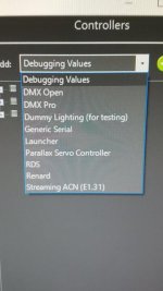
So got it communicating with test patterns. Now for Vixen setup. I'm guessing I won't be using stand e682 patching, so which of these controller types should I add?
Type.jpg

Tried patching as a new DMX controller and no comms with Vixen. Then just tried mapping the next available outputs to single candy cane props for each channel in both Pixel and single LED mode but again no comms to section 4 of the E682. Using DMX standard on the 4th section of the E682 output does control the relays in sequential order on test patterns. Trying DMX pixel yielded random control.

Found a video mostly of what I am doing except not using Vixen. This guy set the universe to 60, hmmm?
https://www.youtube.com/watch?v=e2JXQIOMhfY

So looking at the help page
Similarly, there are protocol converters out there that convert from one protocol to another. For example, the sACN to DMX/Renard bridge will take data in on the sACN protocol via ethernet, and convert and output that data in Renard or DMX formats. In this case, you would need to define the controller as a sACN controller in Vixen. Vixen doesn’t care what happens to the data downstream once it leaves the computer.
I think I should run the mapping as standard E682 pixel commands but use a single object with dumb lighting protocol and the sans will convert it to DMX. We shall see.
Update: That did nothing. :wacko: I can only run tests form the card.
 
Last edited:
So I solved it with help from Jim at Sandevices. Yes you do need the J22 jumper no matter what firmware you are running. My card has a defect on section 4, so I moved DMX to section 3 and universe 9. Remapped Vixen too and now all is well. I guess I was doing things correct but the jumper was masking my results.
 
I am trying this as well.
Can you show me what your mapping in Vixen is?
I am having trouble getting this to work, the relay works when I test on the web interface but not in vixen.
 
Back
Top