Mega 2560 and Vixen 2.1 SSR relays flicker when vixen runs

ok, so with my Mega 2560 and Vixen 2.1 on the computer the SSR relays flicker when vixen runs, they are all on if vixen is off, and when started they work as they should however they all flicker like a strobe constantly until vixen shuts off, then they go back to full on again. what could be my issue.?

I think this is the code im using, its the only one i can find so it must be:

/*
Allow Vixen to control Arduino MEGA outputs.
To control 16 relay channels. RELAY1, RELAY2, etc are the relay control pins.
This version was tested with Vixen 3.
Also eliminated the footer feature. This version only uses a header "~!"
in Vixen 3. In Vixen don't use the quotes, just the two characters.

While Vixen 3 is sending data, the Arduino RX light is ON.
*/

// pinouts used.
#define RELAY1 2
#define RELAY2 3
#define RELAY3 4
#define RELAY4 5
#define RELAY5 6
#define RELAY6 7
#define RELAY7 8
#define RELAY8 9
#define RELAY9 10
#define RELAY10 11
#define RELAY11 12
#define RELAY12 13
#define RELAY13 14 /44
#define RELAY14 15 //45
#define RELAY15 16 //46
#define RELAY16 17 //47

// Configure outputs
int chanDigital[] = {RELAY1, RELAY2, RELAY3, RELAY4, RELAY5, RELAY6, RELAY7, RELAY8, RELAY9, RELAY10, RELAY11, RELAY12, RELAY13, RELAY14, RELAY15, RELAY16};
int vixByte[16]; // size of the channel array
int chanDigitalCount = 16; // Total number of ON/OFF channels.
int i = 0; // Loop counter

//setup the pins/ inputs & outputs
void setup(){
// initalize digital Channel Pins as outputs.
for (i=0; i < chanDigitalCount; i++){
pinMode(chanDigital, OUTPUT);
vixByte = 0; //set array at 255 not 0 for relay OFF by inverting. only if mech relays used. but im using ssr so leave at 0
analogWrite(chanDigital, vixByte); //use either analog or digitalwrite
}

//setup Vixen USB serial port.
Serial.begin(9600);
}

void loop()
{
if (Serial.available() >= chanDigitalCount+1) {
// changed +2 to +1 in above line to have correct channels on relay board
//int uno = Serial.read();
//if (uno == 126){
//int dos = Serial.read();
//if (dos == 33){
// We are now past the header so read and send the 16 channel data.
for (int i=0; i<16; i++) {
// read each byte
vixByte = Serial.read();
analogWrite(chanDigital, 0 + vixByte); //Send to relay pin. use either analog or digitalwrite
}
}
}
//}
//} //end of loop
 
Hard to say. It sounds like you have no synchronization between Vixen and your Arduino.
Did you use the header ~! in your Generic Serial setup?
Is your baudrate 9600 in Vixen?
You should use digitalWrite for zero-cross SSRs.

Edit:
Also, some SSR relays use inverted logic so you may want to verify what your relays need.
 
Last edited:
ok, so with my Mega 2560 and Vixen 2.1 on the computer the SSR relays flicker when vixen runs, they are all on if vixen is off, and when started they work as they should however they all flicker like a strobe constantly until vixen shuts off, then they go back to full on again. what could be my issue.?

I think this is the code im using, its the only one i can find so it must be:

/*
Allow Vixen to control Arduino MEGA outputs.
To control 16 relay channels. RELAY1, RELAY2, etc are the relay control pins.
This version was tested with Vixen 3.
Also eliminated the footer feature. This version only uses a header "~!"
in Vixen 3. In Vixen don't use the quotes, just the two characters.

While Vixen 3 is sending data, the Arduino RX light is ON.
*/

// pinouts used.
#define RELAY1 2
#define RELAY2 3
#define RELAY3 4
#define RELAY4 5
#define RELAY5 6
#define RELAY6 7
#define RELAY7 8
#define RELAY8 9
#define RELAY9 10
#define RELAY10 11
#define RELAY11 12
#define RELAY12 13
#define RELAY13 14 /44
#define RELAY14 15 //45
#define RELAY15 16 //46
#define RELAY16 17 //47

// Configure outputs
int chanDigital[] = {RELAY1, RELAY2, RELAY3, RELAY4, RELAY5, RELAY6, RELAY7, RELAY8, RELAY9, RELAY10, RELAY11, RELAY12, RELAY13, RELAY14, RELAY15, RELAY16};
int vixByte[16]; // size of the channel array
int chanDigitalCount = 16; // Total number of ON/OFF channels.
int i = 0; // Loop counter

//setup the pins/ inputs & outputs
void setup(){
// initalize digital Channel Pins as outputs.
for (i=0; i < chanDigitalCount; i++){
pinMode(chanDigital, OUTPUT);
vixByte = 0; //set array at 255 not 0 for relay OFF by inverting. only if mech relays used. but im using ssr so leave at 0
analogWrite(chanDigital, vixByte); //use either analog or digitalwrite
}

//setup Vixen USB serial port.
Serial.begin(9600);
}

void loop()
{
if (Serial.available() >= chanDigitalCount+1) {
// changed +2 to +1 in above line to have correct channels on relay board
//int uno = Serial.read();
//if (uno == 126){
//int dos = Serial.read();
//if (dos == 33){
// We are now past the header so read and send the 16 channel data.
for (int i=0; i<16; i++) {
// read each byte

vixByte = Serial.read();
analogWrite(chanDigital, 0 + vixByte); //Send to relay pin. use either analog or digitalwrite
}
}
}
//}
//} //end of loop

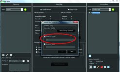
This code was designed to use a header of two characters. That is probably why it checks for serial available +2. You have the header test commented out, so it is not testing for those two characters but the serial available is still lookig for the channel count +1. So the data stream does not look like it is syncing up.
You should un-comment the lines in blue above and change the serial available test back to +2 and make sure you have the header setup in Vixen controller.. Or you could try the code by Victor_PV found here - http://doityourselfchristmas.com/fo...-Up-to-48-realy-SSR-channels-with-Random-mode
 
Also, missing one of the slashes in the comment of this line:
#define RELAY13 14 /44

Although, I'm not sure that would cause the problems you're describing, it may cause problems assigning that pin.
 
update to my issues here: i am using vixen 3.2, i tried also a windows 7 computer its still the same, my board is a 2560 mega sainsmart, and the relays are also sainsmart SSR's .
Kevin above talks about headers ?? no idea what that is.

I made changes as per above but now nothing works, no relay movement, here is the code so far:
/*
Allow Vixen to control Arduino MEGA outputs.
To control 16 relay channels. RELAY1, RELAY2, etc are the relay control pins.
This version was tested with Vixen 3.
Also eliminated the footer feature. This version only uses a header "~!"
in Vixen 3. In Vixen don't use the quotes, just the two characters.

While Vixen 3 is sending data, the Arduino RX light is ON.
*/

// pinouts used.
#define RELAY1 2
#define RELAY2 3
#define RELAY3 4
#define RELAY4 5
#define RELAY5 6
#define RELAY6 7
#define RELAY7 8
#define RELAY8 9
#define RELAY9 10
#define RELAY10 11
#define RELAY11 12
#define RELAY12 13
#define RELAY13 14 //44
#define RELAY14 15 //45
#define RELAY15 16 //46
#define RELAY16 17 //47

// Configure outputs
int chanDigital[] = {RELAY1, RELAY2, RELAY3, RELAY4, RELAY5, RELAY6, RELAY7, RELAY8, RELAY9, RELAY10, RELAY11, RELAY12, RELAY13, RELAY14, RELAY15, RELAY16};
int vixByte[16]; // size of the channel array
int chanDigitalCount = 16; // Total number of ON/OFF channels.
int i = 0; // Loop counter

//setup the pins/ inputs & outputs
void setup(){
// initalize digital Channel Pins as outputs.
for (i=0; i < chanDigitalCount; i++){
pinMode(chanDigital, OUTPUT);
vixByte = 0; //set array at 255 not 0 for relay OFF by inverting. only if mech relays used. but im using ssr so leave at 0
digitalWrite(chanDigital, vixByte); //use either analog or digitalwrite
}

//setup Vixen USB serial port.
Serial.begin(9600);
}

void loop()
{
if (Serial.available() >= chanDigitalCount+1) {
// changed +2 to +1 in above line to have correct channels on relay board
int uno = Serial.read();
if (uno == 126){
int dos = Serial.read();
if (dos == 33){
// We are now past the header so read and send the 16 channel data.
for (int i=0; i<16; i++) {
// read each byte
vixByte = Serial.read();
digitalWrite(chanDigital, 0 + vixByte); //Send to relay pin. use either analog or digitalwrite
}
}
}
}
}
//end of loop
 
Last edited:
update to my issues here: i am using vixen 3.2, i tried also a windows 7 computer its still the same, my board is a 2560 mega sainsmart, and the relays are also sainsmart SSR's .
Kevin above talks about headers ?? no idea what that is.
You add the headers in Vixen in the Generic Serial setup where it has a place for HEADERs and FOOTERs.
 
I'm having a flickering issue and I'm not sure if it's related to this but figured I'd post. I'm brand new to this stuff, and don't know much about electricity haha. So I followed a tutorial and built my first setup with a Mega 2560 and two SainSmart 5V 8 Channel SSRs. I'm using the newest version of Vixen (~3.4).

I haven't had the chance to mess with it much as I have just finished, but when I tested it out yesterday each time a light was supposed to come on, it did but flickered very very quickly. It was almost like a very fast strobe instead of being solid. Same went with the lights on the SSR itself, when the specific channel was supposed to come on, the status light on that channel flickered very quickly.

Anyone know what the issue might be? I have the Arduino powered by plugging in the USB cable into my laptop, and the SSRs are powered by one 5V DC adapter (https://www.amazon.com/gp/product/B0719GY29M/ref=oh_aui_detailpage_o00_s00?ie=UTF8&psc=1)

Thank you all in advance!

What code are you using on your Arduino? What baud? As others have pointed out, did you ensure you have necessary headers?
 
I'm having a flickering issue and I'm not sure if it's related to this but figured I'd post. I'm brand new to this stuff, and don't know much about electricity haha. So I followed a tutorial and built my first setup with a Mega 2560 and two SainSmart 5V 8 Channel SSRs. I'm using the newest version of Vixen (~3.4).

I haven't had the chance to mess with it much as I have just finished, but when I tested it out yesterday each time a light was supposed to come on, it did but flickered very very quickly. It was almost like a very fast strobe instead of being solid. Same went with the lights on the SSR itself, when the specific channel was supposed to come on, the status light on that channel flickered very quickly.

Anyone know what the issue might be? I have the Arduino powered by plugging in the USB cable into my laptop, and the SSRs are powered by one 5V DC adapter (https://www.amazon.com/gp/product/B0719GY29M/ref=oh_aui_detailpage_o00_s00?ie=UTF8&psc=1)

Thank you all in advance!

Do you have the -DC on the SSR boards connected to the GND pin on the MEGA?

A couple of pictures of your hardware setup will help. Also what sketch you are using.
 
Does your sketch have a "power-on" test? If so, does it flicker also?
Does your Vixen sequence use rapid changes?
I'm trying to discern whether the source of your flicker is from Vixen, or your Arduino - SSR setup.
 
Code:
#define MEGA_VIXEN
//#define UNO_VIXEN

#ifdef MEGA_VIXEN
  #define MAX_CHANNELS 52
  int channels[MAX_CHANNELS] = {2,3,4,5,6,7,8,9,10,11,12,13,14,15,16,17,18,19,20,21,22,23,24,25,26,27,28,29,30,31,32,33,34,35,36,37,38,39,40,41,42,43,44,45,46,47,48,49,50,51,52,53};
#endif

#ifdef UNO_VIXEN
  #define MAX_CHANNELS 18
  int channels[MAX_CHANNELS] = {2,3,4,5,6,7,8,9,10,11,12,13,A0,A1,A2,A3,A4,A5};
#endif

int incomingByte[MAX_CHANNELS];

void setup()
{
  int i;
  
  Serial.begin(9600); // set up Serial at 9600 bps

  for ( i = 0; i < MAX_CHANNELS; i ++ )  pinMode(channels[i], OUTPUT);
}

void loop()
{
  int i;
  
  if (Serial.available() >= MAX_CHANNELS)
  {
    for (i=0; i < MAX_CHANNELS; i ++)      incomingByte[i] = Serial.read();
  }

  for (i = 0; i < MAX_CHANNELS; i ++ )    analogWrite(channels[i], incomingByte[i]);
}

That is the code I'm using. If I remember correctly, the baud is 9600. I did plug the -DC into the GND.

I'm also trying to figure out if it's Vixen or the Arduino & SSR that are causing the issue. Is there a way to test the Arduino & SSR without Vixen?
 
You could try bumping up your baud rate, say to 57600 and try again.
9600 baud is 960 bytes per second. Since you have 52 channels, your update is about 18 times a second. Could this be your flicker rate?
 
You could try bumping up your baud rate, say to 57600 and try again.
9600 baud is 960 bytes per second. Since you have 52 channels, your update is about 18 times a second. Could this be your flicker rate?

I actually only have 16 channels, I accidentally posted to original code prior to me changing it to 16. Should I still adjust the baud rate?
 
Back
Top