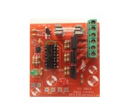
Pixel DCSSR From DIYLEDExpress.com

dlovely

Super Moderator
PixelDCSSR1-3-Final.jpg


The Pixel DCSSR is a DCSSR that uses a WS2811 IC instead of a traditional Renard controller. The Pixel DCSSR functions just as a normal single pixel allowing the control of dumb LED Strings or Strips on a pixel network. You can mix and match the Pixel DCSSR with normal pixels adding them before, after or even in the middle of pixel strings. The Pixel DCSSR has In/Out pads that allow for standard pixel pigtails to be attached. See the Wiki page for more information and build instructions.

Sold in sets of four and can be found at DIYLEDExpress.com. This is not a pre-sale, I have a limited number of kits in stock and ready to ship.
 
Very cool idea (so cool that I just bought some). I really like the thought of only having to run one data (signal) wire to control multiple RGB strips on the house.
 
Hi, I'm a long time lurker, first time poster. I realize this thread is almost a year old, but I just stumbled on it and I feel it is worth a bump because I really like the idea. I think this device has so much potential that I'm breaking my silence to resurrect this topic. :rolleyes:

I'm definitely adding some of these to my pre-order. But all my outdoor strings will be 12v (longer distance, less power injection). Dave, can you please let me know what the resistor swap needs to be in order to run these on 12v pixel strings. I understand why the 2811 power resistor needs to be changed but I'm a little baffled why the signal LED resistor needs to be changed. I thought ALL pixel strings run 5v on the data line even if the power line is 12v. Isn't the signal LED on the data line? FYI, I'll be using an E682 pixel controller if that makes a difference.

I think this device could be extremely useful but probably misunderstood by many. I think there would be more interest in this device if more people understand how it fits in. Any maybe even a desire to have a 2801 (or other) version. As more people move toward more pixel controllers I think this will become more clear.

Here is my plain-English description of what it is/does (please correct me if I'm wrong): :blush2:

1. This device takes the place of one pixel (3-channels) in a 2811 pixel string. Its just another "pixel" in the string.
2. It can be wired anywhere in the string (first, middle, last, does not matter) that any other pixel would fit.
3. Primarily used to add RGB "dumb" strings or RGB floods to an existing RGB "smart" string or pixel string controller.

A few obvious uses I see (and I intend to implement in my setup):

1. Connect an RGB star to a pixel megatree simply by adding this controller to the end of one of the pixel strings. The star would be controlled as another pixel on the string.
2. Connect vertical RGB dumb strips on chimneys (or downspouts or house corners) in the middle of pixel strings that run horizontally across a roofline.
3. Connect RGB floods on the ground between strings of pixel leaping arches.
4. Connect/control multiple RGB floods as though there were a pixel string

Also it could be use in place of a null node to open up new possibilities. Depending on your situation and where you have null nodes, you might put in this instead and add an RGB strip or flood or strobe or just some single-color LED strings and control it just like another pixel on the string.

Very Cool! :biggrin:
 
Last edited:
I'm definitely adding some of these to my pre-order. But all my outdoor strings will be 12v (longer distance, less power injection). Dave, can you please let me know what the resistor swap needs to be in order to run these on 12v pixel strings. I understand why the 2811 power resistor needs to be changed but I'm a little baffled why the signal LED resistor needs to be changed. I thought ALL pixel strings run 5v on the data line even if the power line is 12v. Isn't the signal LED on the data line? FYI, I'll be using an E682 pixel controller if that makes a difference.

The signal LED is not actually on the data line, it is connected to the positive input on the pixel power side, that resistor should change to a 560Ohm and the resistor to the WS2811 should be changed to a 2.7K resistor.

Now if you are using the same 12V to power the DCSSR and the pixels there is really no isolation anymore, so you could run a small jumper wire from the output of the regulator to the +5V pad on the input side. This is what I did as I already had them built up before I changed to 12V. This way you also won't have to worry about any vdrop messing with the WS2811 IC... The reason why the connection was not made on the PCB was to allow complete isolation from the high current side.
 
The signal LED is not actually on the data line, it is connected to the positive input on the pixel power side, that resistor should change to a 560Ohm and the resistor to the WS2811 should be changed to a 2.7K resistor.
Just so I'm not making wrong assumptions, can you please say EXACTLY which resistors (R9? R11?).

Now if you are using the same 12V to power the DCSSR and the pixels there is really no isolation anymore, so you could run a small jumper wire from the output of the regulator to the +5V pad on the input side. This is what I did as I already had them built up before I changed to 12V. This way you also won't have to worry about any vdrop messing with the WS2811 IC... The reason why the connection was not made on the PCB was to allow complete isolation from the high current side.
This makes sense, but again I want to be certain and not assume I understand :blush2:
Datasheet for the regulator says pin 1 is the output and would be on the left when facing the flat side. In the Wiki photos of the PCB it looks like the pin numbers are reversed. If I understand it correctly, the output of the regulator will be closest to the top of the board (and the input comes from a trace off the +V RGB output pad). I don't have an actual PCB in front of me and I realize the Wiki photo may not be the latest version.
 
Just so I'm not making wrong assumptions, can you please say EXACTLY which resistors (R9? R11?).

R11 = 2.7K
R9 = 680 Ohm

This makes sense, but again I want to be certain and not assume I understand :blush2:
Datasheet for the regulator says pin 1 is the output and would be on the left when facing the flat side. In the Wiki photos of the PCB it looks like the pin numbers are reversed. If I understand it correctly, the output of the regulator will be closest to the top of the board (and the input comes from a trace off the +V RGB output pad). I don't have an actual PCB in front of me and I realize the Wiki photo may not be the latest version.

Correct, on the PCB the top pin (Pin 3) is the output. On mine I bridged Pins 1 and 16 (The top, notch side, two pins) on the Opto with a small jumper wire, then just used the Data In/Out and Ground pads on the bottom.
 
Dave I appreciate your fast responses :thup2:

If I jumper from the regulator (or across the top two pins of the opto) then I would leave the resistors as is, correct? I believe we're talking about either/or solutions. EITHER swap the resistors and use +12v from the pixel bus (wired to the +v5 in pad), OR jumper from the regulator and leave the resistors as is (and DO NOT connect the pixel bus power to the +v5 in pad)

Sorry for all the questions. The wiki says "A modification can be made ... to allow for 12V, information about this will be posted once tested." Do you have an official write-up of this mod somewhere that I missed?
 
Last edited:
Dave I appreciate your fast responses :thup2:

If I jumper from the regulator (or across the top two pins of the opto) then I would leave the resistors as is, correct? I believe we're talking about either/or solutions. EITHER swap the resistors and use +12v from the pixel bus (wired to the +v5 in pad), OR jumper from the regulator and leave the resistors as is (and DO NOT connect the pixel bus power to the +v5 in pad)

Sorry for all the questions. The wiki says "A modification can be made ... to allow for 12V, information about this will be posted once tested." Do you have an official write-up of this mod somewhere that I missed?

It is an either or. Doing the jumper if you want to use it on 5V later just remove the jumper wire. I have not had time yet to update that in the wiki. Pretty much when I have time what is said in this thread will be added to the wiki. For now I will add a quick link to this thread.
 
It is an either or. Doing the jumper if you want to use it on 5V later just remove the jumper wire. I have not had time yet to update that in the wiki. Pretty much when I have time what is said in this thread will be added to the wiki. For now I will add a quick link to this thread.
Got it. :happy:

A jumper across the top two pins of the opto seems like the best/easiest/cleanest method. Sounds like a jumper pad there would be nice to include if there is ever a v1.4 :wink:
 
Got it. :happy:

A jumper across the top two pins of the opto seems like the best/easiest/cleanest method. Sounds like a jumper pad there would be nice to include if there is ever a v1.4 :wink:

I actually considered a jumper, but left it out as I thought it would add confusion. Could just see someone installing it and then bridging their 5V and 12V power supplies.... Least this way you are aware of what is going on and is not just a wops.
 
I just bought some of these boards and want to use them with 12v pixel strands. The two pads at the bottom of the board labeled 5+ are not labled "in" and "out". Does this mean that it does not matter which 5+ pad you use for your input or output power wire on the pixel strand?

Also, these pads are still used even when using 12v pixels correct? I think I understand that you just swap resister values in R9 and R11 but keep using those two pads for input power from the 12v strand. The power coming into the DC IN is strictly for whatever is switching for the three channels is unrelated correct?

Thanks for the clarification

The two pads are tied together so it really does not matter what is In or Out. There are just two pads so you can attach two sets of pigtails. The only ones that matter are the Data In/Out.

Yes you use those power pads for 12V it is just labeled 5V since that is what the BOM resistors are set for, going to 12V you need to change those two.

The Power on the SSR side is isolated from the Pixel power side.
 
Got it. :happy:
A jumper across the top two pins of the opto seems like the best/easiest/cleanest method. Sounds like a jumper pad there would be nice to include if there is ever a v1.4 :wink:

I actually considered a jumper, but left it out as I thought it would add confusion. Could just see someone installing it and then bridging their 5V and 12V power supplies.... Least this way you are aware of what is going on and is not just a wops.


Sorry to rehash this but I just wanted to confirm since I have read through this thread several time and am probably overthinking it but if I understand correctly, if you wish to run the board AND the connected dumb LED's with the same 12V power supply all you need to do is jumper pins 1 & 16 on the Opto and do NOT feed power via the 5V terminal on the lower section of the board?

All other components remain unchanged.

Does this look/sound correct?

jumper.jpg

Thank you,


Shane
 
I tried replacing the resistors on the board for 12V operation and the outputs never worked. I was getting 5v on the 2811 but +12V on the outputs, 12v on the opto, and flickering on the pixel output. I then went back to stock resistors and the jumper from regulator pin3 and 5v pad still nothing. I read another post of someone having the same issue with 3 of their boards and no resolution as the thread ends. If I were to try this board again I would do the jumper method leaving the 5v pads empty and +12v pixel power externally connected from the board. This is the only 12v powered pixel method that I have seen confirmed to work on the forums.
 
Back
Top