PixelRadio, a DiY FM Transmitter with RDS RadioText

Any good links to the external on air signs from anyone?
If you want a desk top version then this LED sign looks good: https://www.aliexpress.us/item/2252799820237618.html
For scale, this photo shows the 12V W300xH200mm version:

beautyShot2_1200.png


For outdoor installations you can build your own 12V sign using a backboard populated with LEDs that spell "ON AIR, TUNE TO FM 88.9." Or paint a big sign and illuminate it with bright 12V LED spotlights (that are controlled by PixelRadio).

is the on-air sign similarly hooked up like the LED is so that it turns on when sensing music through the jack?
The external On Air sign control port is synced with the front panel LED. They both turn on whenever the RF carrier is active and the test tone mode is disabled (Music Source enabled).
https://github.com/thomastech/PixelRadio/tree/main/docs/Hardware#on-air-sign

- Thomas
 
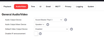
Not getting audio or test tones using the Soundblaster 3. I've set things up in the FPP plugin also.
sb3.png
on air.png
What am I missing?

UPDATE: Turned off Stereo and used Mono and things seem to be ok.
 
Last edited:
UPDATE: Turned off Stereo and used Mono and things seem to be ok.

That is an unexpected solution. Especially since the test tones are independent of the external audio.

At this point it's a mystery on why you need to use the mono broadcast mode. But check / resolder U8, C8, C9, and the QN8027 module. Use the test tones during your troubleshooting since that would eliminate any issues related to external audio.

- Thomas

Ok,using the test tones or audio from the Soundblaster,the audio has alot of static on Stereo. Using mono,the static is there,but way less. I'll have to troubleshoot more tomorrow.
 
Using mono,the static is there,but way less.

Mono mode disables the FM pilot tone and reduces RF bandwidth (better S/N). This improves reception of weak signals and is the main reason the feature exists.

But if you need stereo audio then there might be an easy remedy. For example, perhaps this issue is interference from an adjacent FM broadcaster or dirty RF source. Try tuning to other unused areas of the FM dial. Also try moving the receiver to other test locations that provide better reception. In some situations merely changing antenna position may help.

- Thomas
 
<snip>
Also does the board accommodate 1/4W or is the board designed for the smaller 1/8W resistors? I guess I could always mount them vertically but if this project also expects the smaller ones I might just buy a set.

To answer my own question, the board is designed for 1/8W resistors. 1/4W resistors won't lay flat unless you do some bending or mount them vertically. I got my 1/8W resistors today so all is good :thup2:
 
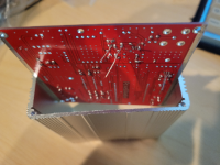
Sorry if this was asked before but there are like 43 pages in this thread. As you can see from the picture I am still working on the board. Terrible soldering (ordered some flux because the solder puddled up high on the soldering iron). My question is regarding the housing, though. There are no guides to put the board in. The board is also a couple of mm to large to squeeze it in (you can see how the housing is actually bending). I have some 'stand off screws' to elevate the board but the fact that it doesn't fit into the housing suggest I am doing something wrong.

board.png

Never mind, I see there is a groove at the very bottom of the case...
 
Last edited:
Sorry if this was asked before but there are like 43 pages in this thread. As you can see from the picture I am still working on the board. Terrible soldering (ordered some flux because the solder puddled up high on the soldering iron). My question is regarding the housing, though. There are no guides to put the board in. The board is also a couple of mm to large to squeeze it in (you can see how the housing is actually bending). I have some 'stand off screws' to elevate the board but the fact that it doesn't fit into the housing suggest I am doing something wrong.

View attachment 46740

Never mind, I see there is a groove at the very bottom of the case...

Hey, don't feel bad. If that is the only mistake you make, your GOOD!
 
Mono mode disables the FM pilot tone and reduces RF bandwidth (better S/N). This improves reception of weak signals and is the main reason the feature exists.

But if you need stereo audio then there might be an easy remedy. For example, perhaps this issue is interference from an adjacent FM broadcaster or dirty RF source. Try tuning to other unused areas of the FM dial. Also try moving the receiver to other test locations that provide better reception. In some situations merely changing antenna position may help.

- Thomas

Re-flowed those those parts I saw,didn't see a U8 on the board or in the BOM,unless I overlooked it,and it didn't make a difference. I did however notice that when my hand or finger was near or touching the L7 jumper wire,there was almost complete silence on Stereo mode.
 
Last edited:
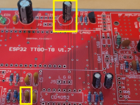
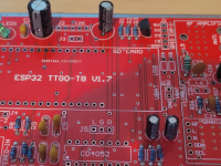
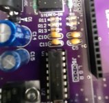
I just be doing something wrong but I am not sure what. C3, the cap in the upper middle is a lot smaller than what the PCB indicates. But it is 100uF/16V from what I can read. Also C10 (lower right) is a lot smaller than the reference image shows. It's a bit confusing because C10 is supposed to be 0.01uF/50V and the other 3 around it are supposed to be 0.01uF/50V so they should be larger. Is C10 just oversized in the reference image (something like 63V or higher)?

20230128_082807.png
 

Attachments

  • 20230128_082807.png
    20230128_082807.png
    471.6 KB · Views: 15
C-10 is .01 uF 50V and C-4,C-5 and C-11 are .1 uF 50V so yes C-10 is larger.
20230128_155505.jpg
And C-3 is 100uF 16V
20230128_155513.jpg
You are not doing anything wrong. I don't want to speak for Thomas but I assume he made changes and for whatever reason the Gerber files were not updated to reflect the changes or something entirely different, but if you stick to the parts list you should be OK.
 
That voltage drop across R1 is valid, but are you sure the resistor value is correct? The expected 470 ohm might have been stuffed with the wrong value, such as 4.7K or 47K. Or maybe a bad solder connection on it. Eyeballs are often the best tool for the job, so check the color code. If unsure then lift one side and measure the resistor value with an ohmmeter.

Sounds like you are measuring the voltage across R2, which will always be zero (MOSFET gates do not draw current). Instead, your meter needs one lead on ground, the other on R2 (check both ends). You should see a bit over 3V on both ends of R2 when the LED is enabled.


Yes, reflow U1 pin 28 (at PCB socket pad and module pad), R1, R2, and Q1. Use solder flux (or fresh solder) to ensure good reflow.

Still not working? Post clear close-up photos of the top and bottom of the board around the R1,R2, Q1, LED1 region. Someone here might spot something.


- Thomas

I stopped working on it for a bit, and decided to work on another one of the boards that I bought (bought multiples of everything) and I had the same result. The color bands were hard to read and I'm PRETTY sure you were spot on that the R1 resistor was incorrect. Waiting for Amazon to ship me some (comparatively overpriced) replacements of the correct ones. Desoldering it was a pain, but I think my board is ready for it. If not....well I have 2 more spares.....

Thanks again - stay tuned.
 
Ok @ThomasLED more LED light woes - I remade a new build again on another board, but this time, the LED is staying on regardless of any input being in the jack. Thoughts?
 
I remade a new build again on another board, but this time, the LED is staying on regardless of any input being in the jack. Thoughts?
Need more info:

1. Does your browser (Firefox, Chrome, Edge) connect to PixelRadio?
2. While connected via the browser: Does the LED turn off when you enable the "Test Tone" Feature?

- Thomas
 
Thanks - perhaps I'm misunderstanding the function of the light then. I thought it was enabled when audio is connected and playing through. Is it just always on when the board is on and not playing test tones?
 
Is it just always on when the board is on and not playing test tones?
That is correct. When the MUSIC ON STATUS LED is illuminated it means that the 3.5mm input jack (music source audio line input) is selected. This LED turns off during test tones as a courtesy warning.

The LED function is summarized here:
https://github.com/thomastech/PixelRadio/blob/main/docs/User_Manual/AdjustTab.md#test-tones
https://github.com/thomastech/PixelRadio/tree/main/docs/Hardware#front-panel-led-music-on-status

- Thomas
 
Totally get it now - I read 'is active' as 'sound is piping through', and not 'input source is active'. That's a me problem. Thanks for everything - can't wait to now use it in my show this year!
 
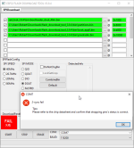
I am trying to upload the firmware to the ESP32 but having some issue. For Windows had an exclamation mark for the serial port. So I downloaded the driver for the CH9102 chip (the chip on the board says CH9102F). After that Windows did not show an exclamation mark anymore. However, when I now tried to run the ESP32 flash download tool v3.9.4 and clicked on START I got a red fail with an error message that popped up (see image). Then the green blinking LED stopped blinking (blue one is still blinking). When I clicked on START again I now got a COM FAIL. Has anyone experienced the same or knows what is going on? Btw, I did remove the board from the PCB so it doesn't have anything to do with the PCB.

PixelRadioFail.png
 
Back
Top