I have a renard ss 24, and I can?t get anything to show up. I have the cat cable in the? input? and the other end the blue/ white is in slot one, blue in slot 2 and both orange cables (orange and orange/white) in slot 5. Not sure what to do here? I?m all ready for this year and can?t get this to work. I even tried a new cat cable. See images.
You are using an out of date browser. It may not display this or other websites correctly.
You should upgrade or use an alternative browser.
You should upgrade or use an alternative browser.
Renard as hook up help!!!!
- Thread starter Jsw2488
- Start date


ChiefWarrant
Supporting Member
I have a renard ss 24, and I can?t get anything to show up. I have the cat cable in the? input? and the other end the blue/ white is in slot one, blue in slot 2 and both orange cables (orange and orange/white) in slot 5. Not sure what to do here? I?m all ready for this year and can?t get this to work. I even tried a new cat cable. See images.
In your photo, the Orange cables appear brown, but that could be just the image.
Some Items to check:
1. Cable pinouts correct.
2. Good crimp on the RJ45 end.
3. Plugged into the correct port of the Renard SS24.
4. Jumper set to accept RS-485 on the Renard.
5. The USB adaptor actually installed correctly under Device Manager.
6. Data rate set correctly on the COM port.
7. You can also validate basic adaptor functionality by measuring appx 6 VDC between Pin 1/2 and pin 5 of the RJ45 end or TX+ and GND on the adapter.
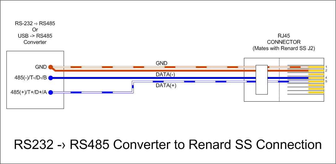
Without a manufacture/model identity of the USB-to-RS485 I am assuming the following:
Pin 1 -> TX+
Pin 2 -> TX-
Pin 3 -> RX+
Pin 4 -> RX-
Pin 5 -> GND
RS-485 End --->Wire Color --------->RJ-45 Pin
Pin 1 -> TX+ --->White Blue----------->Pin 5
Pin 2 -> TX- ---->Blue ----------------->Pin 4
Pin 3 -> RX+
Pin 4 -> RX-
Pin 5 -> GND --->Orange ------------->Pin 2
Pin 5 -> GND --->White Orange ------>Pin 1
Pictured Here
-Tony
Agree -- that looks like the brown pair, not the orange pair.
Also, re: "I have the cat cable in the? input?" Renard SS input is J2. Output is J1. Counterintuitive and throws me every year. I used a sharpie on the enclosure to mark "in" and "out" to remind myself. Not every version of the board has the in and out printed on J1 and J2.
Question: does the adapter have an LED that flickers when it's transmitting data? On my setup, the adapter only recognizes as a COM port if it's plugged in when the computer boots. If I don't see a flicker when I'm playing a sequence, power cycle the computer and good to go.
Sent from my Pixel 5a using Tapatalk
The cables are orange. It just be the lighting. I know I cut the brown ones off. How do I know it?s I. The correct port? This did work 2 years ago. With no problems.
In your photo, the Orange cables appear brown, but that could be just the image.
Some Items to check:
1. Cable pinouts correct.
2. Good crimp on the RJ45 end.
3. Plugged into the correct port of the Renard SS24.
4. Jumper set to accept RS-485 on the Renard.
5. The USB adaptor actually installed correctly under Device Manager.
6. Data rate set correctly on the COM port.
7. You can also validate basic adaptor functionality by measuring appx 6 VDC between Pin 1/2 and pin 5 of the RJ45 end or TX+ and GND on the adapter.
Without a manufacture/model identity of the USB-to-RS485 I am assuming the following:
Pin 1 -> TX+
Pin 2 -> TX-
Pin 3 -> RX+
Pin 4 -> RX-
Pin 5 -> GND
RS-485 End --->Wire Color --------->RJ-45 Pin
Pin 1 -> TX+ --->White Blue----------->Pin 5
Pin 2 -> TX- ---->Blue ----------------->Pin 4
Pin 3 -> RX+
Pin 4 -> RX-
Pin 5 -> GND --->Orange ------------->Pin 2
Pin 5 -> GND --->White Orange ------>Pin 1
Pictured Here
-Tony
So when I look would it be in the j1 or j2? The board doesn’t light up. And it did work 2 years ago just fine.
Agree -- that looks like the brown pair, not the orange pair.
Also, re: "I have the cat cable in the? input?" Renard SS input is J2. Output is J1. Counterintuitive and throws me every year. I used a sharpie on the enclosure to mark "in" and "out" to remind myself. Not every version of the board has the in and out printed on J1 and J2.
Question: does the adapter have an LED that flickers when it's transmitting data? On my setup, the adapter only recognizes as a COM port if it's plugged in when the computer boots. If I don't see a flicker when I'm playing a sequence, power cycle the computer and good to go.
Sent from my Pixel 5a using Tapatalk

In addition to Tony's suggestions (which are excellent) ... where did you get the ss24? If used, are you sure it is flashed with renard 57k firmware?
Which sequencer/player are you using? Are you testing directly or through the schedule module?
I have vixen 3.x
RS-485 adapter to Renard #1 J2(in). Daisy chain to more Renards would be Renard #1 J1(out) to Renard #2 J2(in). Pic you posted looks good. Your board actually has the in/out printed!So when I look would it be in the j1 or j2? The board doesn?t light up. And it did work 2 years ago just fine.
Silly questions:
1. Confirmed COM port of the adapter reported by Device Manager? Windows says it's working?
2. Configure controller in Setup Display to use that COM port? (COM x / 57600 / None / 8 / One) or as appropriate for your firmware...? Enabled? Channel Count right?
3. Mapped your Elements to Controller channels in Setup Display?
Sent from my Pixel 5a using Tapatalk
RS-485 adapter to Renard #1 J2(in). Daisy chain to more Renards would be Renard #1 J1(out) to Renard #2 J2(in). Pic you posted looks good. Your board actually has the in/out printed!
Silly questions:
1. Confirmed COM port of the adapter reported by Device Manager? Windows says it's working?
2. Configure controller in Setup Display to use that COM port? (COM x / 57600 / None / 8 / One) or as appropriate for your firmware...? Enabled? Channel Count right?
3. Mapped your Elements to Controller channels in Setup Display?
Sent from my Pixel 5a using Tapatalk

Everything is mapped. As well. Channels are correct.

It it's been two years since the board was used, try removing each of the socketed components and then re-insert them. This should cut through any corrosion in the sockets or the component pins if any corrosion has happened over the years of storage. It's a quick process...
Last edited:
It it's been two years since the board was used, try removing each of the socket components and then re-insert them. This should cut through any corrosion in the sockets or the component pins if any corrosion has happened over the years of storage. It's a quick process...
I didn?t put the board together. So what do you mean by removing each socket?
Remove the components that are in sockets from those sockets and then re-insert those components in their sockets.
Ok. That?s take me a few minutes and I?ll try to run on then.
Sent from my iPhone using Tapatalk
ChiefWarrant
Supporting Member
Wow. I have not seen the version of board that has the IN/OUT labeled before. I have been using the sharpie method myself.
-Tony
-Tony
Remove the components that are in sockets from those sockets and then re-insert those components in their sockets.
It disconnected everything and reconnected. And the lights and nothing still.
Sent from my iPhone using Tapatalk
Wow. I have not seen the version of board that has the IN/OUT labeled before. I have been using the sharpie method myself.
-Tony
This board was given to me, preassembled by someone I know. I have a 8 ch the same way. And he used it. With no issues.
Sent from my iPhone using Tapatalk
PIC? I had a few shipped that PICs magically dumped firmware somewhere in USPS. "Everything works" before shipping to "Not flashed" at receipt.
Use a PIC with the diagnostic firmware to check the test sequence. Or if you don't have the diagnostic and are feeling brave, move a working PIC to the non-working board.
Also, step through the troubleshooting guide if you haven't already:
http://www.doityourselfchristmas.com/wiki/index.php?title=Troubleshooting_Guide_The_Renard_SS24
Sent from my Pixel 5a using Tapatalk
1) If you have a volt-meter, measure the voltage between the pads labelled 'GND' and '+5V.
2) Inspect the interior of the RJ45 sockets for bent pins.
3) If you're using RS485 to send data to the controller, make sure that JP1 does not have a jumper plug installed (which appears OK in the photo).
4) Try configuring whatever is sending data to the SS24 controllers for each of the other likely baud rages (19200, 28800, 38400, and 115200).
Ignore any of these steps if you've already tried them.