RichieNorthcott
Member
So I have been trying to reverse engineer these boards I have. These use a 4 channel IC so respond the 4 bytes of data rather than the usual three.

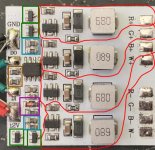
Red - 4 x PT4115 drivers and associated components. My labelling is actually a little misleading since the LED negative connections aren?t common - they are also associated with each of the four sub circuits The is a sample schematic in the data sheet for the PT4115 here:
https://www.electroschematics.com/wp-content/uploads/2014/07/PT4115E-datasheet.pdf
I also note these have been used elsewhere in this forum on the ?20W LED driver? boards, which is more or less this.
Green - NPN transistors interfacing the WS2811 to the drivers
Blue - 10K base current limiting resistors for the transistors
Orange - 51 Ohm resistors on data in / data out lines
Purple - 1K resistor to drop 12V supply voltage to around 5V for IC, and mystery component! See question below....
I have three questions:
What is the component above the 1K resistor? It?s an orange cylinder with a green band on it. It looks like a glass-like material
I was thinking about using these on my garden LED spots - but this would mean long connections between the board and the LED which is probably a very bad idea since that changes the overall inductance i.e the driver ICs assume no notable effect from the connecting cables.
There are two capacitors below the IC connected to ground - I assume this is a way of getting more decoupling capacitance i.e. two in parallel?
Thanks!
Last edited:
