jonthewise
New member
So, I got myself an Arduino Nano 33 IoT, because my wife wants to be able to tell Alexa to change settings on the lights and have it work. I found this tutorial on getting that going https://create.arduino.cc/projecthub/john_dillenburg/arduino-nano-33-iot-12v-ws2811-led-strip-controller-c04f7a and did some research on wiring this up. I got 12v LEDs, and have a 600 watt (12v, 50a) power supply for these. I think I have everything in place to get the right power to the right places (12v to the LEDs, 5v to the Data line, and 3.3v to the Arduino).
I think that I've got the wiring all worked out; When I hook up one string of 50 WS2811 LEDs to pin6, the Arduino NeoPixels stringtest sample seems to work. I can also hook a 100 LED string of WS2811 LEDs that I have to pin 6, and it seems to work as well. Where it goes all wonky is when I hook up one of these to pin6 and the other to pin5. I may be doing it wrong, but I would expect only one of the two strings to run the stringtest, but they're both running it in sync.
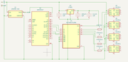
This is my wiring diagram:
I was working on laying it out on a PCB and etching that out, but I haven't quite got there yet, so it's all a tangle of wires on a breadboard right now. Ignore the Raspberry Pi. Unless the answer is that I should be using that instead.

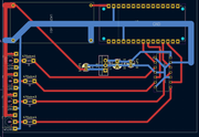
This is the PCB plan, in case you want to critique my work before I go off and etch it - I have 100mm x 70mm double-sided boards for this.
Basically, since the Nano 33 only has 3.3vs of power, and the signal wire is a 5v signal, I've got a logic level shifter. And since my LEDs are 12v, I've got a little L7805 circuit to create a 5 volt reference signal for the logic level shifter. In the schematic, you see a LM2596 to convert the 12v power to 3.3v for the Arduino, but on the breadboard I'm just using USB to power it. Also, for some reason when I have the resistor plugged in to the board between the shifter and the second WS2811 string, there's an issue where it acts like there's a short - if I hold the resistor just right, it starts to light up some of the string, but if I pull it out and just feed the data directly from the shifter it works fine; I presume this is an issue with the connection between the tiny resistor wires and the breadboard, and that I'm just lucky that the other resistor seems to be sending a perfect signal.
Right now I'm just using the NeoPixels library from Adafruit, but I'm not opposed to using something else.
I posted a quick clip of what I'm seeing here: https://youtu.be/3umF02l0RzY
Any thoughts on why both strings are lighting up at the same time? Any suggestions for how I should be doing things differently? I can use the Raspberry PI that's connected to the breadboard if that makes more sense, I'd still need the logic level shifter, from what I understand, because it still puts out a 3.3v signal, but I could use the 5v signal for reference instead of having the whole L7805 circuit in place to get 5v from the 12v supply.
I'm really just looking for some direction from someone that's actually done this before on how to keep this as simple and functional as possible - I want to power a lot of lights (hence the 50amp power supply) but it doesn't do me much good if I can't control them
I think that I've got the wiring all worked out; When I hook up one string of 50 WS2811 LEDs to pin6, the Arduino NeoPixels stringtest sample seems to work. I can also hook a 100 LED string of WS2811 LEDs that I have to pin 6, and it seems to work as well. Where it goes all wonky is when I hook up one of these to pin6 and the other to pin5. I may be doing it wrong, but I would expect only one of the two strings to run the stringtest, but they're both running it in sync.
This is my wiring diagram:
I was working on laying it out on a PCB and etching that out, but I haven't quite got there yet, so it's all a tangle of wires on a breadboard right now. Ignore the Raspberry Pi. Unless the answer is that I should be using that instead.
This is the PCB plan, in case you want to critique my work before I go off and etch it - I have 100mm x 70mm double-sided boards for this.
Basically, since the Nano 33 only has 3.3vs of power, and the signal wire is a 5v signal, I've got a logic level shifter. And since my LEDs are 12v, I've got a little L7805 circuit to create a 5 volt reference signal for the logic level shifter. In the schematic, you see a LM2596 to convert the 12v power to 3.3v for the Arduino, but on the breadboard I'm just using USB to power it. Also, for some reason when I have the resistor plugged in to the board between the shifter and the second WS2811 string, there's an issue where it acts like there's a short - if I hold the resistor just right, it starts to light up some of the string, but if I pull it out and just feed the data directly from the shifter it works fine; I presume this is an issue with the connection between the tiny resistor wires and the breadboard, and that I'm just lucky that the other resistor seems to be sending a perfect signal.
Right now I'm just using the NeoPixels library from Adafruit, but I'm not opposed to using something else.
I posted a quick clip of what I'm seeing here: https://youtu.be/3umF02l0RzY
Any thoughts on why both strings are lighting up at the same time? Any suggestions for how I should be doing things differently? I can use the Raspberry PI that's connected to the breadboard if that makes more sense, I'd still need the logic level shifter, from what I understand, because it still puts out a 3.3v signal, but I could use the 5v signal for reference instead of having the whole L7805 circuit in place to get 5v from the 12v supply.
I'm really just looking for some direction from someone that's actually done this before on how to keep this as simple and functional as possible - I want to power a lot of lights (hence the 50amp power supply) but it doesn't do me much good if I can't control them