wireless SSR?

dstokesdubois

New member
I currently have two renards running 20 SSrez's. I'm going to use raspberry PI's to run my pixels wireless and would like to also get rid of the cat6 between the renard and the ssr. Anybody know of an wireless SSr ?
 
What is a wireless SSR? Do you mean something more like a small wireless controller which would fit in an SSR box?

That is, an SSRez is basically a 4 channel Triac board which is controlled by 4 logic level signals; the timing of the logic level (sync'ed to AC) requires an external controller. Doing that level of control (4 logic level triggers for triacs) wirelessly doesn't make a lot of sense. You kinda need a uC to handle the OTA protocol, at which point why not handle the dimming/timing locally as well (ie: become a real controller).

I recently proposed a 4 channel wireless dimming controller; it would have 4 or 6 VO2223A opto-triacs, another optocoupler for zero cross detect, an Arduino Pro Micro or ATMega328, an nRF24L01+ transceiver, and a 120 VAC->5V (or 3.3v) power supply. It would use the Komby protocol over the air, and it would handle dimming those channels. The goal was to fit into the same size box as an SSRez or similar SSR, with no ethernet cable (tho I've since realized that a somewhat more waterproof box would work, since there's no need to plug a cable in). I have NOT built this (on the stack), but I have tested the tricky parts of the coding. I chose the opto-triac because I would only be dimming small loads, like LED strings or short incans, so a small and cheap Optotriac could work; others might prefer a real external triac for more power.

Is this (small, low channel count, low cost wireless AC dimming controller which externally looks more like an SSR box) the kind of thing you are really looking for? Nobody mentioned anything in exactly that niche, but a miniREN + wireless adapter comes fairly close. And maybe someday I'll build my concept, if somebody else doesn't first.
 
Last edited:
The MiniRen8/4 is small (about 3" x 3.5") and has 4 on-board triacs so it's pretty close to a wireless SSR. You can plug an XBee radio into it, one of Komby's wireless gizmos if you want to use his control system or an ESP Snap-In if you want full Wi-Fi use.

http://digwdf.com/store/product.php?id_product=13


Alternately, you could connect a DIGWDF ESP Thing to the DIGWDF ZCSSR and have essentially the same thing that would handle even more current.

ESP Thing: http://digwdf.com/store/product.php?id_product=220
ZCSSR: http://digwdf.com/store/product.php?id_product=228


At DIGWDF we specialize in weird things.
 
Rather than Arduino Pro/Mega, I suggest using ESP8266 (e.g. Wemos D1 mini). It has Wifi builtin, small form-factor, and plenty of GPIO pins.
 
Rather than Arduino Pro/Mega, I suggest using ESP8266 (e.g. Wemos D1 mini). It has Wifi builtin, small form-factor, and plenty of GPIO pins.

Has anyone found a way to implement multi-channel AC dimming control with an ESP8266? That is, detect zero crossing, and and control 4 (or more) triacs with proper timing to each?

The challenge with the ESP8266 is that it needs to share the CPU between the wireless side and the user code side, making tight timing more difficult. If someone has found a way to do this, it would make using an ESP8266 in this way very interesting!

Thus the first DIGWDF solution uses a wireless snapin to convey serial data to the PIC on board with the Triacs (the PIC handles the timing), while in the second solution the wireless adapter has the PIC to do the timing. Neither works without the PIC. Both are cool solutions tho! But it would be really minimal if we could use just the esp8266 as you suggest.
 
Last edited:
It depends on whether you're looking for something that works "right now," or whether you're looking for a "project to develop." Sounds to me like more of the latter. Go for it. Make it work.
 
The MiniRen8/4 is small (about 3" x 3.5") and has 4 on-board triacs so it's pretty close to a wireless SSR. You can plug an XBee radio into it, one of Komby's wireless gizmos if you want to use his control system or an ESP Snap-In if you want full Wi-Fi use.

http://digwdf.com/store/product.php?id_product=13


Alternately, you could connect a DIGWDF ESP Thing to the DIGWDF ZCSSR and have essentially the same thing that would handle even more current.

ESP Thing: http://digwdf.com/store/product.php?id_product=220
ZCSSR: http://digwdf.com/store/product.php?id_product=228


At DIGWDF we specialize in weird things.

Since he already has 20 SSRez's, would another solution be to use a TINYREN8XB Board with the ESP Snap-In along with SSRez's that he already has?


Sent from my iPad using Tapatalk
 
Yes, that could work fine, too, although you'd need to provide a ZC signal to the TinyRen if it's going to work with AC lights and dimming. Of course, the DIGWDF store has a ZC kit too....

....we specialize in having the weird circuit boards and kits....
 
Hi, it should be possible to use an ESP to switch a few channels, the fun bit is doing it without interrupts and not missing the new packet or the zero cross pulse. The hard part daft as it sounds looks like it will be if no AC is connected, once it is and a zero cross pulse has been detected we know when the next one is due and can go back and loop until we see it. With no AC connected it would be stuck in the loop and the WDT (Watch Dog Timer) would kick in. I suppose not a problem if the ESP is powered indirectly from the mains.
Now Christmas and my son’s birthday are out of the way I'll have some time to do an evaluation of this. I don't have a H11A1 on the bench so I'll have to simulate the high pulse this with another device. Can someone confirm the real world spec for this pulse please. I’ll work on 100uS until this is confirmed.
 
Hi, it should be possible to use an ESP to switch a few channels, the fun bit is doing it without interrupts and not missing the new packet or the zero cross pulse.... I don't have a H11A1 on the bench so I'll have to simulate the high pulse this with another device. Can someone confirm the real world spec for this pulse please. I’ll work on 100uS until this is confirmed.

I would like to hear more about your thought on this, perhaps in another thread so as not to hijack this one. There seem to be several challenges in doing this without a hardware timer and with interrupt limitations - while needing to yield() frequently enough and for long enough to keep the wireless stack happy, and fetching/interpreting received packets.
 
Hi, mainly @ Zeph but feel free to comment. @ dstokesdubois, if this is distracting from the thread I'm happy to move it and just leave a link.

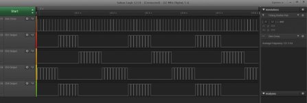
I got a couple of hours this evening to have a play and this looks very possible. I’ve posted my first attempt development code below which went far better than I had expected. It captures the E1.31 packets, triggers on a simulated zero cross signal and combines the two to generate output triggers for triacs.

Problems / to-dos:
Some of the timing needs adjusting but mainly because it wasn’t worth doing until the next problem is sorted.

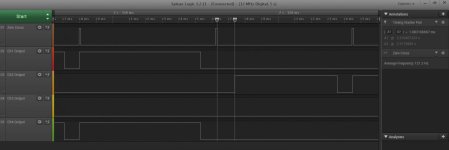
The e1.31.parsePacket needs speeding up or splitting up as causes a 1mS delay in the output when a packet arrives. This means that a 255 high output to the triac which should last about 8mS only lasts 7mS, more like a 223. At 40FPS or 25mS timing this means you end up with 223, 255, 255, 223, 255, 255 instead of 255,255,255,255,255,255. TBH I’m not sure this would be noticeable to most people as it’s at the high end of the light output where it has least visual impact. If I can’t improve the speed and this is noticeable I can always apply a derating so the maximum is 223, this would result in a 12% reduction in light output (compared to maximum), but given various post where people have commented that they can reduce the output to nearly 50% without noticing a difference it shouldn’t be a problem. It would only really affect floods.

Anyway below: Screen grab of four outputs (255 value) with an RGB chase input. Screen grab of the 1mS delay when we parsePacket. The first attempt at code.
AC_SSR_dev1_1.jpg
AC_SSR_dev1_2.jpg
Code:
#include <ESP8266WiFi.h>
#include <E131.h>

// set the pin numbers of the in / outputs
int output_1 = 12; // pin number of output 1 to triac
int output_2 = 13; // pin number of output 2 to triac
int output_3 = 14; // pin number of output 3 to triac
int output_4 = 15; // pin number of output 4 to triac
int input_zc = 4; // pin number of zero cross input

// variables for the DMX value
int channel_value_1;
int channel_value_2;
int channel_value_3;
int channel_value_4;

// general variables
long int num_channels; // number of E1.31 values in packet
int loop_number; // keeps track of number of times looped
unsigned int step_ends; // single loop timer
unsigned int step_delay = 30; // delay for 60Hz

// E1.31 setup
const char ssid[] = "<YOUR_SSID>"; // AP SSID
const char passphrase[] = "<YOUR_PASSWORD>"; // AP password
const int universe = 1; // universe number
const int channel = 0; // start channel
E131 e131;

void setup() {
// set the function & state of the in / output pins
  pinMode(input_zc, INPUT); // set pin as output
  pinMode(output_1, OUTPUT); // set pin as output
  pinMode(output_2, OUTPUT); // set pin as output
  pinMode(output_3, OUTPUT); // set pin as output
  pinMode(output_4, OUTPUT); // set pin as output
  digitalWrite(output_1, LOW);  // set output low / off
  digitalWrite(output_2, LOW);  // set output low / off
  digitalWrite(output_3, LOW);  // set output low / off
  digitalWrite(output_4, LOW);  // set output low / off
  // select unicast or multicast - one must be commented out
  //e131.begin(ssid, passphrase); // unicast 
  e131.beginMulticast(ssid, passphrase, universe); // multicast 
}

void loop() {
  while (digitalRead(input_zc) == 0) { // loop untill zero cross
    step_ends = micros(); // time in micros now
  }
     num_channels = e131.parsePacket();
  if (num_channels) {
    channel_value_1 = (e131.data[channel + 0]);
    channel_value_2 = (e131.data[channel + 1]);
    channel_value_3 = (e131.data[channel + 2]);
    channel_value_4 = (e131.data[channel + 3]);
  }

  do {
    // switch on output / triac if we have waited long enough
    if (loop_number == channel_value_1)
      digitalWrite(output_1, HIGH);   // set output high / on
    if (loop_number == channel_value_2)
      digitalWrite(output_2, HIGH);   // set output high / on
    if (loop_number == channel_value_3)
      digitalWrite(output_3, HIGH);   // set output high / on
    if (loop_number == channel_value_4)
      digitalWrite(output_4, HIGH);   // set output high / on

    step_ends += step_delay;          // add delay to time to get end time
    while (micros() < step_ends);     // check time now against end time & wait
    loop_number--;                    // reduce loop counter by 1
  } while (loop_number > 10);         // 'do' it all again unless ==0

  digitalWrite(output_1, LOW);        // set output low / off
  digitalWrite(output_2, LOW);        // set output low / off
  digitalWrite(output_3, LOW);        // set output low / off
  digitalWrite(output_4, LOW);        // set output low / off
  loop_number = 255;                  // start value for loop counter
}
 
Last edited:
Back
Top