Looking for schematic to connect uSD board to D1 Mini. I'm having too much lag on a few ESPixelSticks (D1 Mini) and my FPP and remotes are "spot on" so I want to move my e131 ESPixelSticks to be V4 FPP Remote ESPixelSticks. Does anyone have a schematic they can share, or pointers on how to wire. Appreciate.
You are using an out of date browser. It may not display this or other websites correctly.
You should upgrade or use an alternative browser.
You should upgrade or use an alternative browser.
Connecting uSD to D1 Mini - need pin connections
- Thread starter mrGrumpy
- Start date
MartinMueller2003
Supporting Member
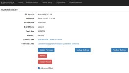
load V4 on your d1 mini. Open the UI on your browser. On the admin page select "advanced". Go back to the device page. You will see the GPIOs used to access the SD card.
Ok, massaging the learning curve and I have my assemble working the EFFECTS, but with a 3-5 second delay between actions, after clicking save.
Won't play FSEQ or Remote Sequence File.
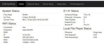
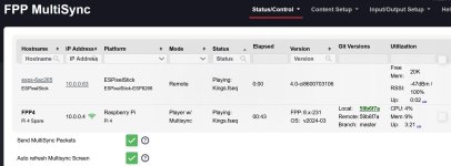
FPP shows the ESP as a remote and playing, but no lights or elapse time. also ESP status doesn't show packets...I think it should.
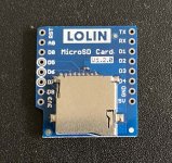
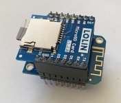
Few Pics - hope they can help you answer some question to where I've gone wrong.
Won't play FSEQ or Remote Sequence File.
FPP shows the ESP as a remote and playing, but no lights or elapse time. also ESP status doesn't show packets...I think it should.
Few Pics - hope they can help you answer some question to where I've gone wrong.
Attachments
MartinMueller2003
Supporting Member
You would see an FPP sync count if the device was in FPP remote mode. You have it set to play from the local file. How did you create the fseq file? If you click on Advanced mode and go back to the status page, you will see an additional field called last error. I would bet you have a compressed fseq file. The error will tell you that we do not support the compressed file. It could also tell you that the file is not a proper FPP V2 file. The last possibility is that this is not a "Sparse" file. A sparse file contains only the channel data that the ESP needs to output on its own port. A non sparse file will output unexpected data.
Yes, going Sparce and non-compressed got me light and correct elapse timing but they it's not reliable. It runs for a while then drops out. If I go back to "device setup" the FSEQ File to Play is empty. To get "FSEQ Files to Play" again, I need to reselect "SD Chip Select Pin" and test until I get one that works.
Select, Save, Reload check FSEQ File to Play.
Select, Save, Reload check FSEQ File to Play.
MartinMueller2003
Supporting Member
Please keep a console connected to the device and capture the output. I cannot quite understand your description of the symptoms.
Sorry, I don't understand this. Please keep a console connected to the device and capture the output.
1. EFFECTS seems to work fine except there is a 5 second delay changing after I make a change (solid to rainbow) and click save.
2. For Play Remote Sequence, it seems to crash and drop the selected Play Remote Sequence, then there is no selection in that field. I need to reselect a new SD Chip Select Pin
MartinMueller2003
Supporting Member
1) The 5 second delay is expected when you are making changes from the UI. It takes time to transfer the config to the esp.
2) That makes very little sense. I have been using that functionality for a long time. Tat is why I want to see the console output to see what the esp is complaining about. Are you using the flash tool to upload your image? The flash tool logs all of the console output. Just leave the flashtool connected to the ESP and send me the logs after it crashes.
Also, please post a copy of the admin page.
MartinMueller2003
Supporting Member
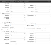
In the pictures above I see the SD CS and the Pixel port both on GPIO 2. What is the correct number for these? They cannot both be on GPIO2.
MartinMueller2003
Supporting Member
It looks like the GPIO is selectable. If you bridge the pin to GPIO 15 then everything should work. Right now the Filesystem and the output channel are fighting over the same GPIO and that causes a deadlock with a watchdog reboot.
MartinMueller2003
Supporting Member
Looks like the default GPIO is 0 (zero). That is a risky choice but it will work as long as the device has a pullup resistor on it.
MartinMueller2003
Supporting Member
Let me simplify things then. I am going to create a build in the dist called d1_mini_lolinsd that will have the GPIOs set the way you need them for this SD card.
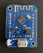
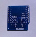
If you want to try using GPIO 15, there are solder pads on the back of the card. Unshort the GPIO0 connection (sharp knife) and add a solder bridge between the center and gpio15 marked pad in the setting block on the back of the board.
If you want to try using GPIO 15, there are solder pads on the back of the card. Unshort the GPIO0 connection (sharp knife) and add a solder bridge between the center and gpio15 marked pad in the setting block on the back of the board.
MartinMueller2003
Supporting Member
You can find the build in this dist file

 github.com
Release Added mrGrumpy D1_mini Plus LoLin uSD card platform · MartinMueller2003/ESPixelStick
Added mrGrumpy D1_mini Plus LoLin uSD card platform Added Tetra2go platform Added missing platforms in the build process. Finalized Config merge in the UI. Fixed issue that causes ESP8266 to crash ...
github.com
MartinMueller2003
Supporting Member
FYI: The dist using GPIO 0 is available so you do not need to change the card.
MartinMueller2003
Supporting Member
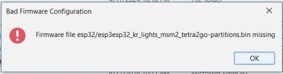
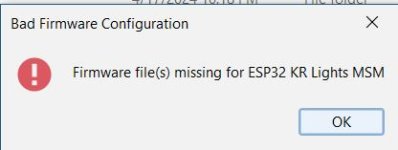
Nope nothing wrong. I get those on occasion as well. you can ignore them.