Dipole Antenna Build and Clarifications

JaxLax

New member
Since this hobby is *technically* my sons (9yo) - it's his responsibility to push, build, modify everything within reason. He wants to upgrade the antenna and sound from last year - and I think I've got it all figured out. This way I can have all the BOM on hand and steps laid out for him to succeed.

Last year we used a Whole House Transmitter 3.0 (sitting on a light fixture outside the garage ~45' from street) off a Pi4 audio jack. It was sufficient. You'd get sound a few houses down the street and it was strong enough in front.

This year the Pi4 and WH FM3.0 are moving out into the yard in a CG1500 mounted on the megatree pole and also adding a Soundblaster Play3. Looking to go to a dipole antenna attached to a literal tree about 10' away from the megatree pole. This will get the antenna 10' from the street. Following along here HOW TO MAKE A DIPOLE FM TRANSMITTER ANTENNA looks to be where we will go, but that leaves a few clarifications and questions.

We'd need to get:
1. STA to coax adapter for the connection at the WH FM 3.0
2. 1:1 balun? THIS GUY MAYBE? to connect the coax and then use the outputs in the T for the antenna. Is there a reason to go 4:1?

I'm envisioning running the coax from the FM3.0 out the CG1500, down the pole, across some grass, then up into the PVC T, connecting at the balun. Reading the instructions for the antenna build, we could alter steps 8-12 to rather than clipping off the excess steel cable (would still solder to keep in place/maintain tension) - take the excess directly into the top connections for the linked balun.

Does this make sense with a good chance of being a successful project? I like to have stuff like this for him over the summer in the garage (rainy days in FL) to do on his own and keep him working on problems. Lots of short steps that can be start/stop and picked up later so it looks like a great one for him.

Thanks in advance for any ideas or suggestions.
 
Low-power FM transmitters are by their nature, well, low power. That means there isn't a lot of juice going out to the antenna. With such low-power RF devices you want the cable from the transmitter to the antenna to be as short as you can conveniently make it because the cable itself has resistance and will use up some of that energy, leaving less energy to go to the antenna.

It's far better to run a long audio line out to the transmitter that's close to the antenna than it is to put the transmitter indoors and run a long antenna cable out to the antenna. You don't have 50,000 watts available where burning a few watts by having a long cable won't make a difference. You have a fraction of a watt to start with. A dipole antenna isn't going to help you if all your power is used by by the cabling.
 
If you decide to install the DiY dipole antenna (I would certainly do it) then get a SMA to F-Connector adapter. This will allow you to use RG6 (lowest loss but stiff) or RG59 (slightly more loss, but flexible) coax to connect the antenna to your transmitter. Skip the Balun, you will not need it.

RG6 has -2dB loss per 100 feet. So typically not an issue for a broadcast FM RF application. However, your FCC compliant FM transmitter is working with flea power (microwatts!). So as mentioned, keep the coax as short as practical.

Ideally you would only use enough coax to attach the antenna (a few inches). But it sounds like you prefer to mount the transmitter on the megatree pole and the antenna 10' away from it. So assuming you only use 20' (or less) of RG6, and do a good job of terminating all the RF connectors, I think you will be satisfied with the results.

- Thomas

-2db is equivalent to 66% signal loss. That's pretty significant with any transmitter. So yeah, put the transmitter out there where the antenna is and run a long audio cable to the transmitter. You'll get a lot less loss on the audio cable over longer distances than you will RF energy.
 
I'm going to build this antenna using a similar guide. Mr Creed Diploe. I like his guide as it include a frequency converter to tell you the exact length of wire and poles based on the FM channel you transmit. This way I can mount it in my attic and run coax to the garage where the transmitter sits. He mentions making sure to use an isolated 75/300 ohm converter with the center conductor going to the upper array wire. Makes sense.
 
I stopped using Dipole antennas a long time ago. Built a ground plane antenna (actually simpler for me) and got much better performance without changing my transmitter. Antenna hangs from a tree branch and is staked into a bed of pachysandras that grow under the tree.
 
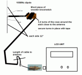
This is a very simple di-pole that I still use for my EDM transmitter. I get 1/2 mile out of it without any trouble. Easy to make and works great IMO.
 

Attachments

  • EDMdipole1.gif
    EDMdipole1.gif
    37.2 KB · Views: 17
I'm curious about using the 75 to 300 ohm matching adapter. Since we are using lower wattage (someone said "micro-watts") for our transmitters, does the adapter further weigh down the signal?

FYI - The antenna I had didn't have any adapter, but was wired directly to the antenna wires (as in the Wiki article) and then the output of the transmitter.
 
I've always thought that the transmitters worked best with a 50 ohm load. At least the instructions that accompany the transmitters usually suggest that.
 
I think that was a misprint, I have never seen a 50 ohm to 300 matching transformer. RF coax is normally 75 ohm, even RG6 triple shielded. There is db loss at every mechanical connection; normally -3 db (or half power). Soldered connections are less and are preferred where possible. I would just pay attention to which of the terminals has the least resistance to the center conductor and make sure it ties to the upper array.
 
Ahhhhh... but antenna matching is a matter of impedence, not resistance. Resistance can block the power that goes to the antenna. The good news is that at the very low levels that these transmitters output, there's not a lot of resulting difference whether it's 50 or 75 ohms, although there is *some*.
 
Impedance matching is measured in Ohms (minus the J factor). Yes it is a factor in determining optimal RF transmission and in AC transducers. If the cable you are using has a 50 ohm impedance rating, you should use a matching transformer adapter, otherwise you will get some standing waves. Just make sure they match whether you 50 or 75 ohm cable.
 
Back
Top