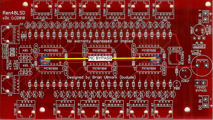
Ren48LSDv3c: Difference between revisions
No edit summary |
m Removed a duplicate phrase. |
||
| Line 162: | Line 162: | ||
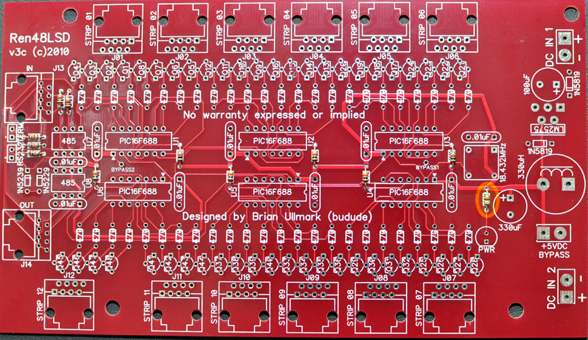
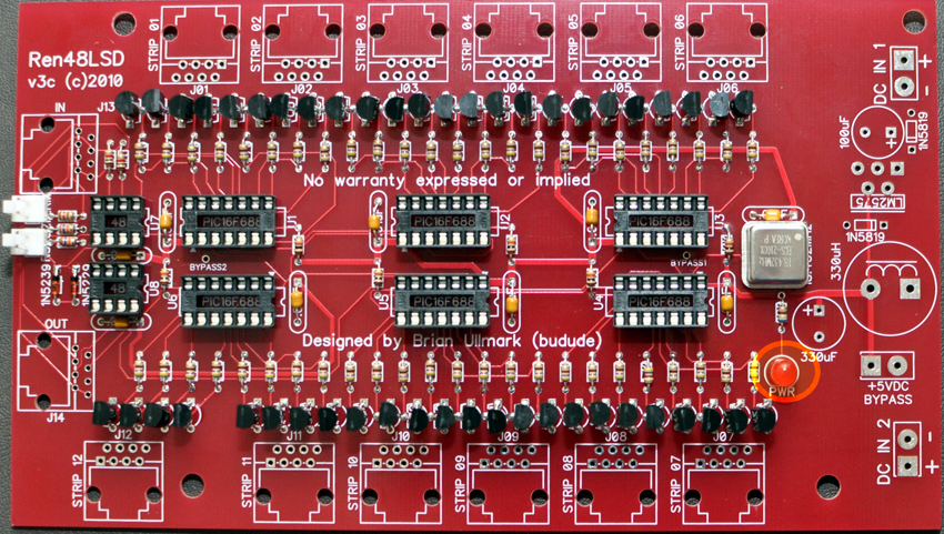
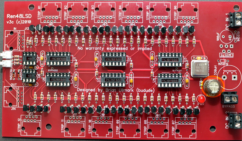
21. Install the 330uF/16v capacitor – | 21. Install the 330uF/16v capacitor – note correct orientation - the capacitor has a stripe on the side denoting the negative leg that goes in the round hole. | ||
[[File:Ren48LSD-v3c-Build-21a.jpg|850px]] | [[File:Ren48LSD-v3c-Build-21a.jpg|850px]] | ||
Revision as of 00:28, 19 April 2011
Ren48LSD (v3c) Construction Manual
What is the Ren48LSD?
The Ren48LSD (LED Strip Driver) controller came about as a solution to drive Frank's LED Super Strips. Originally I used DCSSRs to drive them and while it's a workable solution, it tends to be somewhat bulky and requires lots of additional wiring between the controller and DCSSRs as well as to the strips themselves. Another alternative is Frank's Ren24LV which uses ULN2803 drivers. The issue with this solution is that it has limitations in how much power it can sink to the strips due to the ULN2803 package power dissipation.
The strips require up to 360mA per output (18 LEDs x 20mA) so I used an NPN bipolar transistor to drive them. The transistors support up to 600mA so there's plenty of headroom left. The transistors are fairly cheap so it makes for a simple, inexpensive solution. The controller design used the Ren24SS as a base, using the same PIC, clocking and serial interface configuration but expanded to 6 PICs to support 48 channels or driving up to 12 strips per board. Because of this, the controller supports standard Renard protocol FW using RS-232/485 as well as the DMX version. The board requires either a 5vdc well regulated supply or a good 9-24vdc supply. The input supply also drives the LED strips.
For information on the previous version of this board (v3b) please go to Ren48LSD. This page is for the v3c version of the board.
Revision History
The main changes from the v3b version of the board are a newly designed voltage regulator circuit. It was found on the v3b that the standard LM7805 regulator would get very hot when fully loaded at 12v (the v3b only supported 5vdc or 9-12vdc input). When fully on, the device sat at it's peak temperature of about 120 degC. I came up with a few workarounds which addressed this (see the v3b page) but for the next revision, I decided to change the regulator completely. Instead of using a linear 7805 regulator, I went with the LM2575-5 switching regulator. While it requires a few more parts (a coil, diodes and low ESR filter capacitors) it does allow the v3c version of the board to go up to 24vdc at full load. The regulator stays well within the temperature specs and in normal operation does not even get warm.
You do have to decide prior to building the board whether you will be using +5vdc or 9-24vdc as your input supply source (specifically to DC IN 1). If you are going with 5vdc, then you don't need any of the regulator circuit components - in fact you should specifically leave them off the board. There is a bypass jumper block on the board that bypasses the +5v from DC IN 1 directly to the logic on the board so you must install that block and jumper that as well. If you are going with 9-24vdc then you do need to install all of the regulator circuit to provide 5v to the logic on the board (PICs, Oscillator, RS485 chips).
Ren48LSD (v3c) Parts
In addition to the PCB, you will need the following components:
| Mouser BOM | ||
| Mouser PN | Description | Qty |
| 579-PIC16F688-I/P | Microcontrollers (MCU) 7KB 256 RAM 12 I/O | 6 |
| 571-1-390261-3 | IC & Component Sockets 14P ECONOMY TIN | 6 |
| 511-ST485BN | Buffers & Line Drivers Hi-Spd Lo Pwr Trans | 2 |
| 571-1-390261-2 | IC & Component Sockets 8P ECONOMY TIN | 2 |
| 520-TCH1843-X | ECS-2100AX-18.432MHZ | 1 |
| 863-MPS2222AG | Bipolar Transistors 600mA 75V NPN | 48 |
| 78-1N5239B | Zener Diodes 9.1 Volt 0.5 Watt | 1 |
| 78-1N5229B | Zener Diodes 4.3 Volt 0.5 Watt | 1 |
| 863-1N5819G | Schottky (Diodes & Rectifiers) 1A 40V | 2 |
| 863-LM2575TV-5G | Switching Converters, Regulators & Controllers 5V 1A PWR SW REG | 1 |
| 532-577102B00 | Heatsinks TO-220 HORIZ/VERT SLIM CHANNEL STYLE | 1 |
| 604-WP7113ID | Standard LED - Through Hole HI EFF RED DIFFUSED | 1 |
| 581-SA105E104MAR | Multilayer Ceramic Capacitors (MLCC) - Leaded 50volts 0.1uF 20% Z5U | 9 |
| 667-ELC-18B331L | Power Inductors 330UH RADIAL COIL CHOKE | 1 |
| 140-RXJ331M1CBK1012P | Aluminum Electrolytic Capacitors - Leaded 16V 330uF 105C 10x12.5 mm | 1 |
| 140-RXJ101M1HBK1016P | Aluminum Electrolytic Capacitors - Leaded 50V 100uF 105C 10x16 mm | 1 |
| 299-680-RC | Carbon Film Resistors 680ohms | 1 |
| 299-120-RC | Carbon Film Resistors 120ohms | 1 |
| 299-27K-RC | Carbon Film Resistors 27Kohms | 2 |
| 299-1K-RC | Carbon Film Resistors 1.0Kohms | 2 |
| 299-470-RC | Carbon Film Resistors 470ohms | 48 |
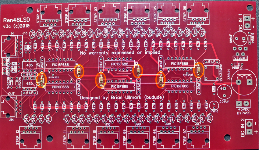
| 299-10K-RC | Carbon Film Resistors 10Kohms | 6 |
| 571-5556416-1 | Telecom & Ethernet Connectors 8 PCB TOP ENTRY | 14 |
| 571-7969492 | Terminal Blocks 5.08MM VERTICAL 2P wire protector | 3 |
| 571-5-146281-2 | Headers & Wire Housings 2 P HEADER GOLD 30u single row | 2 |
| 649-65474-002LF | Headers & Wire Housings SHUNT TIN | 1 |
Most of the components are not overly critical and some can be omitted in certain cases. The electrolytic capacitors must only be subsituted with low-ESR versions only. Failure to do so could result in instability in the regulation circuit. If you are using a well regulated 5vdc supply, the voltage regulator, 1N5819 diodes (2), 330uH coil, and 100uf capacitor should not be installed. This will require a jumper to be placed across the +5vdc bypass terminal block which effectively shunts DC IN 1 directly to the board logic.
Building the Ren48LSD
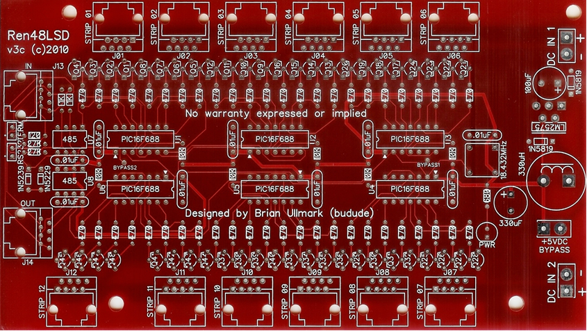
The Ren48LSD requires a fair bit of soldering so take your time and ensure you install the components in the correct orientation when required. Start by sorting the components by type and values. Look over the PCB before starting noting the location of the various components. Follow the standard procedure of installing the lowest profile parts first and ending up with the tallest.
1. Install the six 10k resistors near each PIC
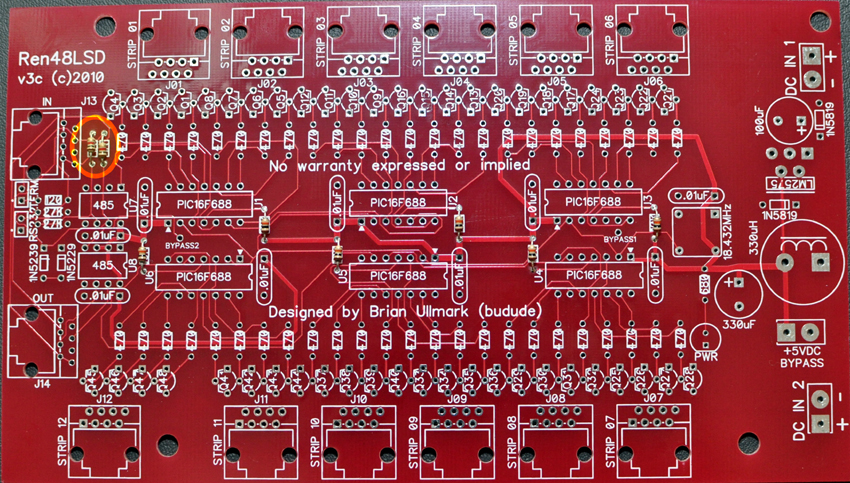
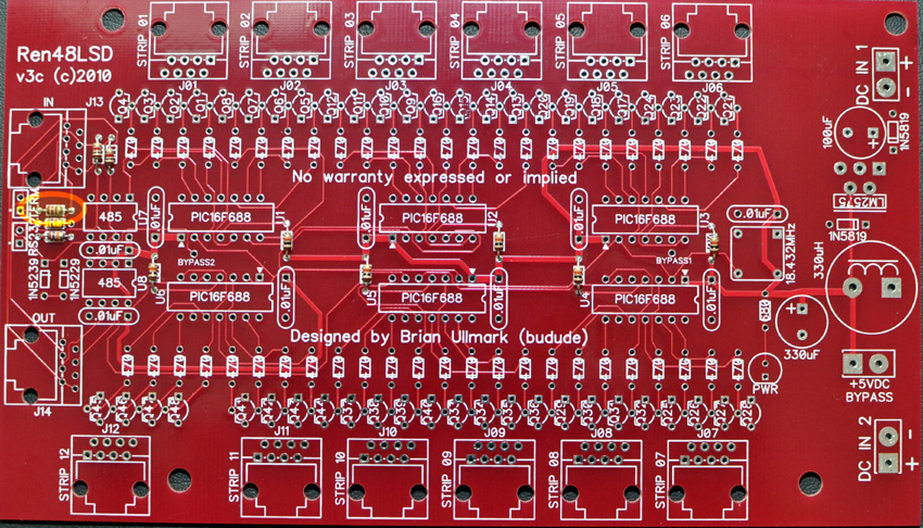
2. Install the two 1k resistors near the 485 chips
3. Install the two 27k resistors near the 485 chips
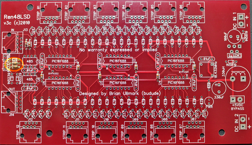
4. Install the one 120 resistor near the 485 chips
5. Install the one 680 resistor near the LED
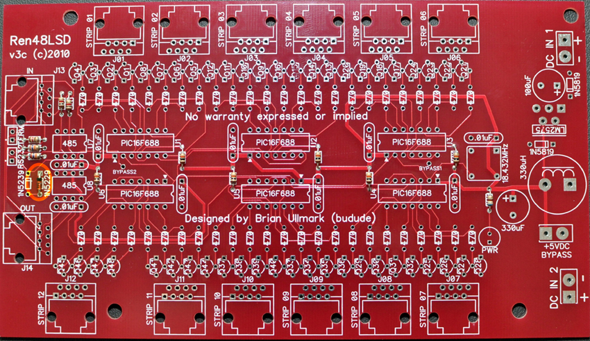
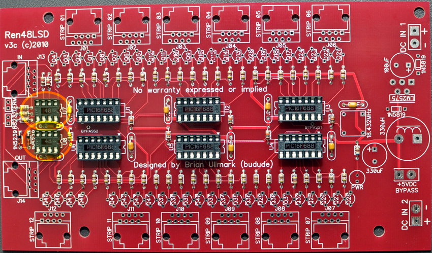
6. Install the 1N5229 diode near the 485 chips – note the correct orientation - the band on the diode goes towards the top of the board in the square hole.
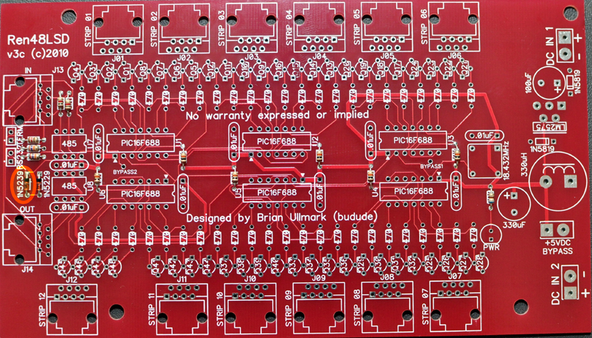
7. Install the 1N5239 diode near the 485 chips – note the correct orientation - the band on the diode goes towards the top of the board in the square hole.
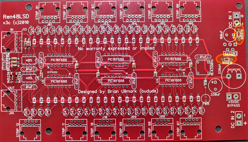
8. Install the two 1N5819 diodes near the voltage regulator (Do not install for 5vdc input) – note the correct orientation - the diode closest to DCIN1 has the band on the diode facing down and in the square hole, the diode closest to the choke has the band on the diode facing right and in the square hole.
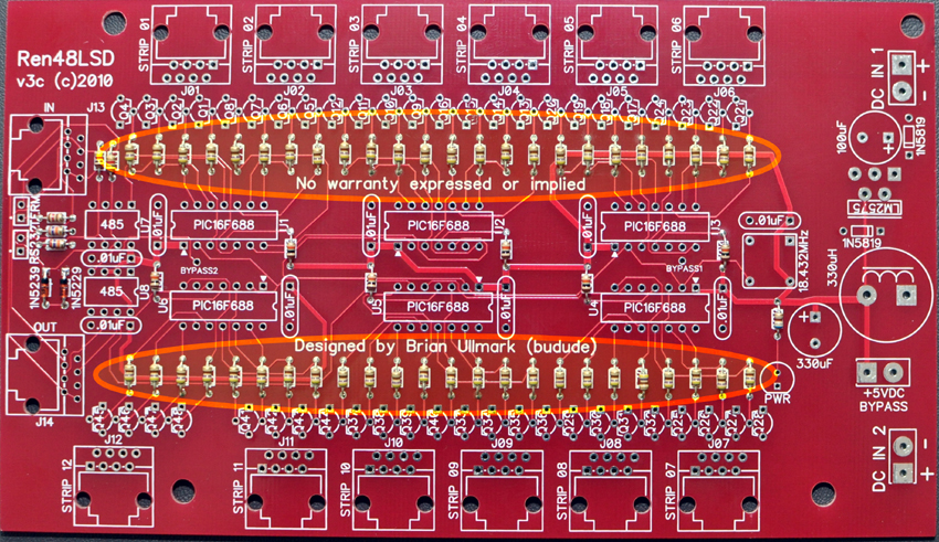
9. Install all forty-eight 470 ohm resistors doing 4-8 at a time.
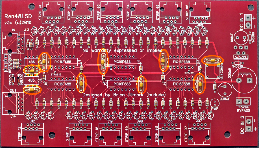
10. Install the nine decoupling capacitors near the IC sockets and oscillator. Note that the silkscreen says ".01uF" - in fact they are 0.1uF (100nF).
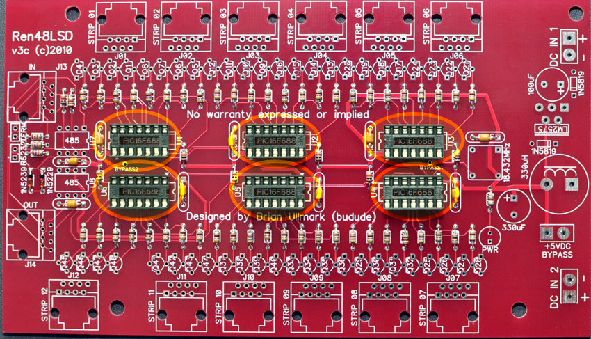
11. Install the six 14-pin PIC chip sockets - note the correct orientation - the top 3 sockets have the notch facing towards the left, and the bottom 3 sockets have the notch facing the right.
12. Install the two 8-pin 485 chip sockets - note the correct orientation - the notch faces to the right side of the board towards the PICs.
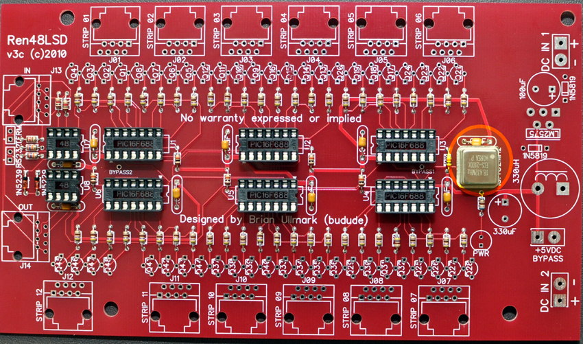
13. Install the 18.432MHz oscillator – note the correct orientation - the package has one square corner (and a dot) and that goes into the square hole on the board
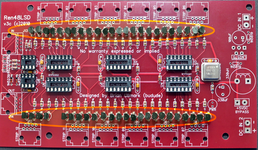
14. Install the 48 transistors – note the correct orientation – the emitter is nearest the PICs, base in the middle and collector near the RJ45 jacks. The legs of the transistors will need to be bent slightly to fit the holes. The middle leg will end up being out in front of the flat side of the transistor.
15. Install the two 2-pin shunt jumpers
16. Install the LED – note correct orientation - the flat side of the diode faces the bottom of the board.
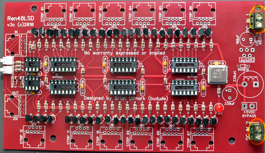
17. Install the DC input terminal blocks – note correct orientation - have the side where the power wires will be inserted facing to the right.
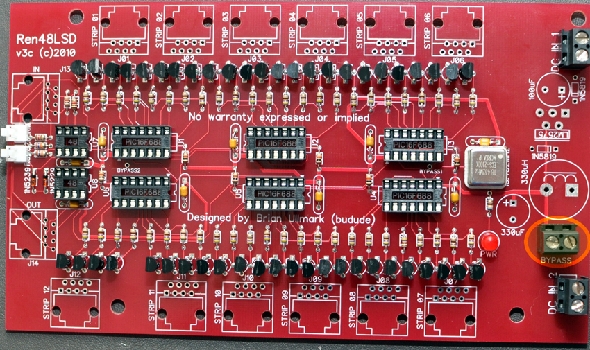
18. Install the +5vdc bypass block (Install for 5vdc input)
Note that if you are using a regulated 5vdc power supply for your input, you should omit installing most of the regulator circuitry.
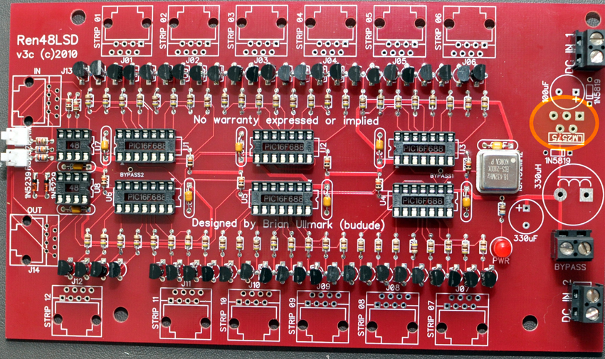
19. Install the LM2575 regulator (Do not install for 5vdc input) - note correct orientation - pin 1 is denoted by the square pad - the odd number pins are the pins farthest away from the back
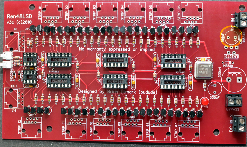
20. Install the 100uF/50v capacitor (Do not install for 5vdc input) – note correct orientation - the capacitor has a stripe on the side denoting the negative leg that goes in the round hole.
21. Install the 330uF/16v capacitor – note correct orientation - the capacitor has a stripe on the side denoting the negative leg that goes in the round hole.
22. Mount the 5v regulator heat sink if you installed the regulator – use a small amount of heat sink compound
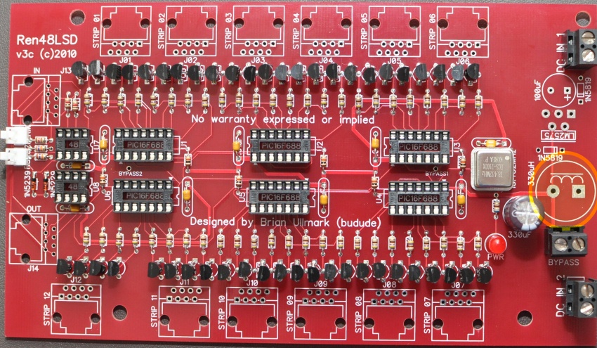
23. Install the choke coil (Do not install for 5vdc input)
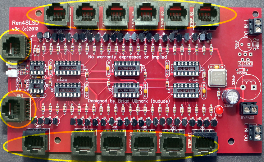
24. Install the fourteen RJ45 jacks – note that side-entry jacks can be substituted
Congratulations! That completes the construction of the Ren48LSD!
Initial Testing
The first thing you will want to do in any PCB construction project is to double check that you have all components installed and in the proper orientation. You will then want to inspect the board for any cold/bridged solder joints. Take your time with this step and go over each and every joint.
If you have any of the IC's installed - remove them now. Connect your power supply to the “DC IN 1” - it supplies power to controller portion of the board as well as strip outputs 1-6. “DC IN 2” is a separate input to drive strips 7-12. Note that the ground is shared between the two inputs. If you are using a well regulated +5vdc power supply as your power input, the regulator circuit should not be installed. However, you must manually bypass this by placing a jumper wire between the +5vdc bypass terminal block. Turn on the supply and verify the power LED lights up. Verify you have 5v between pins 1 and 14 on each PIC socket as well as between pins 5 and 8 on the 485 chip sockets. Install all of the IC's if this passes.
Programming the PIC controllers
The Ren48LSD does not supply or use a ZeroCross input and therefore the Renard firmware (either Renard or DMX protocol) must be configured for DC/PWM operation. In addition, if you are using the DMX firmware, you may want to set the initial starting address but generally, this can be left at '1' for all PICs since the code is self-addressing. Also – like the ULN2803 drivers, the transistors invert the output so the firmware uses positive outputs.
Renard Protocol
Obtain the standard Renard firmware here:
Make the following changes:
#define PWM_build 1 – change from '0'
#define DC_build 1 – change from '0'
#define CTR_LOCKOUT 1 – change from '15'
;#define OUTPUT_NEGATIVE_TRUE – comment this out
Compile the code into hex code and program all six PICs with the same code. A standard version of the code with the settings above has been compiled already for you in the File Library available here.
Renard-DMX Protocol
Obtain the DMX Renard firmware from here:
#define DC_build 1 – change from '0'
#define CTR_LOCKOUT 0 – change from '40'
#define SINK_map 0x00 – change from '0xFF'
If you want to change the DMX starting address then alter it below – this is only required on the first PIC in the chain. If you have multiple Ren48LSD controllers, you can leave the second/subsequent PICs at '1' and they will automatically start off where the last PIC left off.
#define DMX_START_ADDRESS 1
Compile the code into hex code and program all six PICs with the same code (unless using a starting address). A standard version of the code with the settings above has been compiled already for you in the File Library available here.
Whichever firmware you choose, install the flashed PICs into the sockets noting the correct orientation. Also install the two 485 chips into their sockets noting the correct orientation. You are now ready for final testing.
Final Testing
I chose not to design in the diagnostic LEDs as those used on the RenSS series of controllers. The design is fairly straight-forward and as long as you are sure of the voltage inputs and the PICs are flashed properly you should not have any issues if your soldering is good.
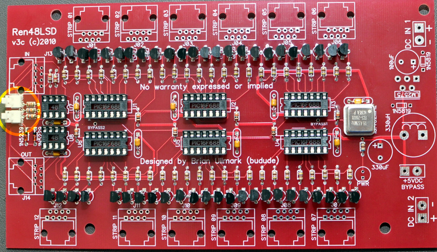
If you are using RS232, you should install the shunt on the "RS232" header which shorts pin 5 of the RJ45-IN connector to ground for proper RS232 operation. The wiring is the same as the RenardSS series so you can follow the cabling requiremnents for that.
As the Renard controller variations do not use bussed DMX it's not critical to install the DMX termination shunt if you are only using Renard controllers. This is because they are using point-to-point configurations. However - if this particular controller is at the end of a line of other normal (bussed) DMX devices, you should install the shunt to properly terminate the bus.
I'm assuming at this point that you have built one or more of the LED SuperStrips to test with. If not - - well - - do it... Note that the strips have one caveat – I have found that the LED colors go in Red, Blue, Green and White order – not Red, Green, Blue and White order. The RJ45 outputs are as follows:
- Common +DC
- Red Ground
- Common +DC
- Blue Ground
- Common +DC
- Green Ground
- Common +DC
- White Ground
What does this mean to you? Well – if you use standard straight-thru RJ45/Ethernet cables, the color order will be RBGW channel order in Vixen so if you want to use an RGBW order, you'll need to change the channel order in Vixen. The other alternative (and the way I do it) is to swap pins 4 and 6 at one end of the RJ45 cable. I did this because I thought it made more sense to keep the natural pin order versus color order. Note that pins 1, 3, 5 and 7 are tied together both on the PCB as well as the strips – there is no way to have separate +DC runs with the strips.
Connect the Ren48LSD to your PC using standard wiring practices as on the Wiki for other Renard controllers. Develop a Vixen sequence to turn on/off each channel in groups of four using the appropriate Renard/DMX plug-in. Channels 1, 5, 9, etc should have the same programming but only have 1 channel in the group (1,2,3,4) on at a time. This helps ensure you have unique channel addressing from each RJ45 output.
With the sequence running, plug in a strip into each RJ45 and ensure each color turns on in order (remember that the B & G colors are swapped). Once that is complete you change the on/off to ramp up/downs to verify dimming operation. Finally, you can perform a full load test with 12 strips installed.
FAQ
Q1: What if I only have 6 strips?
A1: Well - you're in luck! Next to PIC #3 and PIC #6 is a via hole that will bypass PICs #4 - #6 if you install a wire between them. Note that this is only necessary if you are planning to daisy-chain another board from this one. This effectively makes this a Ren24LSD. If you are not going to daisy-chain another board, you can leave it off as well as the RS-485 output chip. Personally, I think this is false economy since you'll have to dig the parts up if you change your mind and want to run a board off this one. In either case, you certainly save time and money by not installing the PICs, sockets, transistors, resistors and output connectors for strips 7-12 if you don't have them.
Q2: Can I use standard DIY SSRs with the Ren48LSD?
A2: Maybe - but with the following caveats:
- It has not been tested at all
- The power LED on the SSR will not work as there is no ground fed to pin 7.
- To be safe, pins 3, 5 and 7 should not be connected from the Ren48LSD to the SSR.
- You may want to stick with a 5vdc source only if insure of the specifications of the optoisolators used on the SSRs. If you are using the standard coop AC or DC SSRs then they should be able to use anything up to 12vdc OK.
For these reasons, it is not really recommended to use an SSR on the Ren48LSD at this time.
Schematic
Here is the schematic drawing for the Ren48LSD v3c in PDF format - File:Ren48LSD-v3c-Schematic.pdf
--Budude 03:08, 4 June 2010 (UTC)
