10W-RGB-LED-DRIVER: Difference between revisions
Ukewarrior (talk | contribs) |
Ukewarrior (talk | contribs) |
||
| (4 intermediate revisions by the same user not shown) | |||
| Line 133: | Line 133: | ||
. | . | ||
== Testing your board == | == Testing & Trouble Shooting your board == | ||
After your initial build, you can test your board with a 12V DC input and a jumper wire.<br> | After your initial build, you can test your board with a 12V DC input and a jumper wire.<br> | ||
| Line 139: | Line 139: | ||
[https://www.youtube.com/watch?v=7VIRZ_iPhG4&feature=youtu.be Initial test video] | [https://www.youtube.com/watch?v=7VIRZ_iPhG4&feature=youtu.be Initial test video] | ||
<br><br> | <br><br> | ||
Sometimes, you will solder everything, but find that one color isn't working.<br> | '''Sometimes, you will solder everything, but find that one color isn't working.'''<br> | ||
The most common reasons for missing color: | The most common reasons for missing color: | ||
Floating IC pin. | Floating IC pin. Inspect each pin to make sure it is properly soldered.<br> | ||
Wet pins. Sometimes flux will stay under the IC and will conduct just enough current to prevent IC from working correctly. <br> | Wet pins. Sometimes flux will stay under the IC and will conduct just enough current to prevent IC from working correctly. <br> | ||
Touch each pin with soldering iron for ~2-3 seconds... or just wait an hour or 2.<br> | Touch each pin with soldering iron for ~2-3 seconds... or just wait an hour or 2.<br> | ||
| Line 148: | Line 148: | ||
Wet with flux and touch with iron for ~2 sec. On occasion, solder will get under the IC. <br> | Wet with flux and touch with iron for ~2 sec. On occasion, solder will get under the IC. <br> | ||
In that case, you can try flux several times and if that doesn't help, just desolder the IC. <br> | In that case, you can try flux several times and if that doesn't help, just desolder the IC. <br> | ||
HOWEVER, | HOWEVER, Desoldering the IC may damage PCB, so skillet, oven or hot air is the best method.<br><br> | ||
'''Here is another experience on how to fix initial trouble with a board:'''<br> | |||
''I built ten boards. Four did not work originally. Three were solder issues with the PT4115. I fixed these by using a cue tip to add flux to both the PT4115 and solder wick and using a clean tip draw excess solder off the PT4115. They looked fine but this worked on three of the problem boards. On the fourth board I powered it on and then using a jumper cable started working backwards from the led. Turned out that I had a cold solder joint on the diode. Re-flowing from the bottom of the board did not fix it. I had to do a re-flow from the top.'' | |||
== Installation examples == | == Installation examples == | ||
Latest revision as of 21:05, 6 March 2015
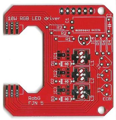
A Constant Current Driver Board for 10W RGB Modules
This circuit board is specifically designed to drive 10W RGB LED modules.
It has the ability to drive a 10W RGB LED via a 5v DC PWM signal that will allow
dimming of each individual color.
As a separate LED driving power source is applied to the board, three additional connections are made to the board that can
control the brightness of each color separately.
These connections are typically the 5V DC output pins from a microcontroller.
This board works with the Ren32/64/48LSD and most RGB strip controllers.
Mostly through hole, inverted inputs (no software tweaks required,) and off when no signal.
The boards are designed to fit standard 10W LED flood light enclosures.
10W RGB LED
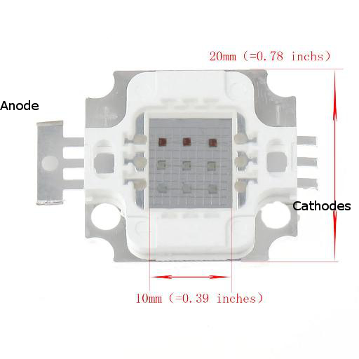
This board was specifically designed for a commonly found 10W RGB, common anode, LED.
These square form factor LEDs can be found at many online stores, ebay and aliexpress.
This board was designed to the dimensions shown in the picture to the right.
Typically characteristics of these LEDs would be:
Color: RGB
DC Forward Voltage (VF): Red 6-8V, Green 9-12V, Blue 9-12V
DC Forward current (IF): 300MA
Output Lumens: Red 120-150LM, Green 200-300LM, Blue 70-100LM
Wave Length : Red 620-625nm , Green 515-520nm, Blue 455-460nm
Beam Angel: 140 degrees
Life span: >50,000 hours
As you can see from the picture to the right, these LEDs are not very large,
less than 1" square.
All three colors have a common Anode (+), and separate Cathodes (-) for each color.
When using this LED with the 10W Driver board, you need to remove the bar along the anodes that tie them together.
Do NOT snip the anodes themselves off. Just the linking bar. When you are done, both sides of the LED should look the same.
Despite their size, do not be fooled into thinking these are like regular indicator LEDs that you see on circuit boards.
These units can generate enough heat to burn themselves out if not attached to a heatsink.
BOM - Bill of Materials
The BOM for this board uses both surface mount(smd) and through-hole components.
The only mandatory smd part is the constant current driver IC, the PT4115.
The board can use either through-hole or smd inductors. The BOM shows through-hole inductors.
BOM for 12V DC power input:
QTY    Board ID           Description
3      IC1,IC2,IC3        PT4115 by Powtech: 30V, 1.2A Step-down High Brightness LED Driver with 5000:1 Dimming
3      L1,L2,L3           100uH Inductor, 6x8mm, 500ma
3      T1,T2,T3           Transistor  FJN3314R
3      D1,D2,D3           Diode    1N5819
3      R1,R2,R3           Resistor, 1/4 Watt, 0.33 Ohm, 5% or better, carbon or metal film
3      R4,R5,R6           Resistor, 1/4 Watt, 4.7K (4K7) Ohm, 5% or better, carbon or metal film
1      IC4                Voltage Regulator, 5V 78L05
1      C1                 Electrolytic Capacitor 100uF 35v (polarized)
1      C2                 MLCC Ceramic Capacitor .1uF  50v (monolithic)
Assembly Tips
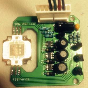
Here is an assembly guide created by livermore-dad.
Click to download -> Assembly Guide
This board has only one part that will take some small amount of skill to install, the PT4115.
While this is an smd part, it can be hand soldered successfully.
To do so, you will need, some liquid flux.
This is the only part that really needs the liquid flux, however, you may also find it useful when you solder the LED.
The LED can be mounted to the top or the bottom of the board.
It may not seem like much, but this clearance difference can be a key to success when retrofitting this board into a repurposed LED Flood Light assembly.
Mounting the LED:
The LED has it's Anodes to the top of the board (near the "10W RGB LED driver" silkscreen) and the Cathodes along the bottom (near the "RobG" silkscreen).
Soldering Sequence
This is a pretty simple board with only a few components.
However, if you do nothing else, solder the PT4115 IC's first.
The trick to soldering these little fellows are to:
1. Use some liquid flux on the pads
2. Use a fine, clean, tip on your soldering iron
3. Use VERY LITTLE SOLDER ! A fine gauge solder would be helpful
You should concentrate on tacking down one of the the outermost pads (not the center pad) to hold the IC in place.
Once you do this, the rest will be much easier.
After that, simply follow the typical sequence of lowest to tallest components.
Do the resistors, the diodes, the transistors, the capacitors, the inductors and finally the LED.
Wiring examples
Note !! This section is under assembly and will be greatly expanded
General Notes
The RGB inputs are strictly 5V DC Maximum only.
So, that is a total of 3 * 5V power sources.
These do NOT power the LED, they only trigger the IC to do its thing.
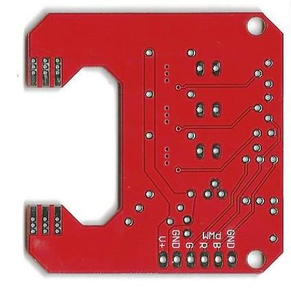
These are labeled (on the back of the board) as: PWM/R G B
The board also requires one DC power source to drive the LED. One for the whole board.
This should be a 1A capable power source.
This is labeled (on the back of the board) as: V+
All of the grounds need to be tied together. Namely, the 5V grounds, the 12V ground and the ground on the board.
While there are two ground connections on the board, they are indeed tied together and are the same.
There are two possible attachment points.
These are labeled (on the back of the board) as: GND
REN48LSD connections

.
Testing & Trouble Shooting your board
After your initial build, you can test your board with a 12V DC input and a jumper wire.
Here is a link to a YouTube Video that shows this test.
Initial test video
Sometimes, you will solder everything, but find that one color isn't working.
The most common reasons for missing color:
Floating IC pin. Inspect each pin to make sure it is properly soldered.
Wet pins. Sometimes flux will stay under the IC and will conduct just enough current to prevent IC from working correctly.
Touch each pin with soldering iron for ~2-3 seconds... or just wait an hour or 2.
Resin from the core of the solder: Some resins will conduct, so clean all remaining resin with rubbing alcohol.
Shorted pins. Little droplets of solder can get stuck between pins (sometimes hidden by resin.)
Wet with flux and touch with iron for ~2 sec. On occasion, solder will get under the IC.
In that case, you can try flux several times and if that doesn't help, just desolder the IC.
HOWEVER, Desoldering the IC may damage PCB, so skillet, oven or hot air is the best method.
Here is another experience on how to fix initial trouble with a board:
I built ten boards. Four did not work originally. Three were solder issues with the PT4115. I fixed these by using a cue tip to add flux to both the PT4115 and solder wick and using a clean tip draw excess solder off the PT4115. They looked fine but this worked on three of the problem boards. On the fourth board I powered it on and then using a jumper cable started working backwards from the led. Turned out that I had a cold solder joint on the diode. Re-flowing from the bottom of the board did not fix it. I had to do a re-flow from the top.
Installation examples
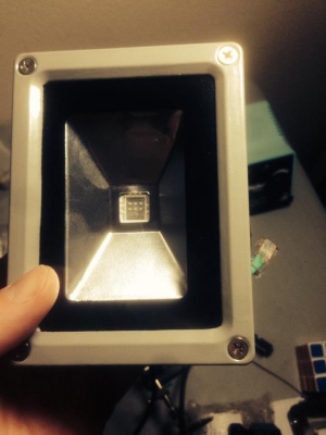

.
Schematic
Here is the Schematic diagram as captured from EAGLE.
Click here to download the schematic as a pdf: File:10w fjn5 sch-1.pdf
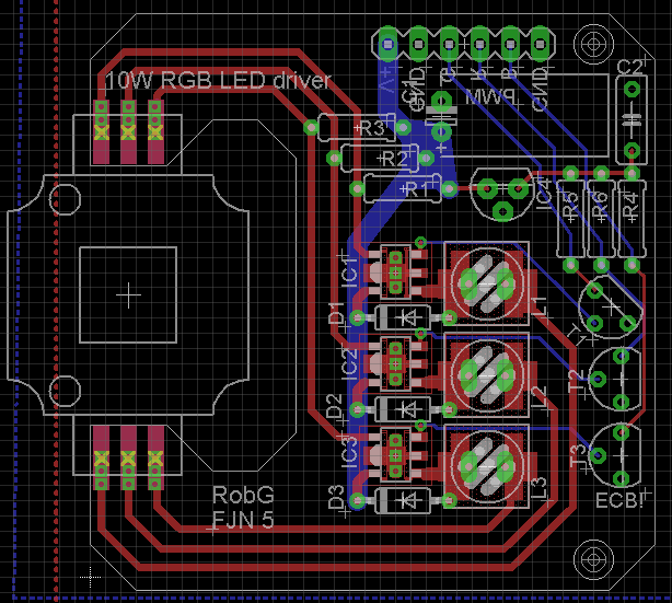
.
Where can I get one of these wonderful boards?
This board was created by Robert Gasiorowski.
He has allowed group buys from time to time on DIYC. You can PM ukewarrior at DIYC to see if there is a group buy in process.
Where there is no group buy in progress, you can usually get this board in a full DIY kit at Rob's Tindie store. His store can be found at: Rob's Tindie Store page.