Renard 64XC Construction: Difference between revisions
m (moved REN64Construction to Renard 64XC Construction: first was a working title while developing the page) |
m (→Board Assembly) |
||
| (43 intermediate revisions by 4 users not shown) | |||
| Line 1: | Line 1: | ||
==Board Assembly== | ==Board Assembly== | ||
: | ::'''Note:''' Pictures are being added daily and the sequence is changing based on an actual assembly. | ||
:'''NOTE:''' The part numbers referenced in the following instructions are those taken from the [[ | :The following sequence of steps is by no means the only way to assemble the Renard 64. It is simply a suggested order of assembly. Many builders have varied opinions on what the order should be. In general, you start with the "shortest" items and work towards the tallest. This generally means that resistors are first and connectors are last but every board is different. | ||
:A good temperature controlled soldering iron should be used for building the Renard 64. Try to get the smallest diameter rosin core solder you can find (either 60/40 or 63/37). PLEASE DO NOT USE LEAD FREE SOLDER!! This takes special equipment and a very high skill set that few DIYers have. If you do use Lead Free Solder and have problems (which is VERY likely) please let us know when you ask for help. Lead Free Solder can look like a good joint but still be a problem. | |||
:One safety note is prudent here. Solder is METAL (lead and tin)...In order to use it,it must be MELTED. HOT, Molten Metal can BURN! Also, metal leads get hot while soldering. So, any unprotected fingers that are being used to "hold" a component in place will be burned!! Painter's tape is one way of holding items down while the board is being flipped over. Another way is to use another unpopulated board or flat surface to allow the board to be flipped while keeping the components in place. | |||
:'''NOTE:''' The part numbers referenced in the following instructions are those taken from the [[Renard_64XC#Bill_of_Materials | Renard 64 BOM]]. | |||
{| border="0" cellpadding="10" style="text-align: left;" | {| border="0" cellpadding="10" style="text-align: left;" | ||
!width="200"| | |||
!width="300"| | !width="300"| | ||
|- | |- | ||
| | | | ||
* Start by checking the PCB over for any obvious production faults. Check for traces that end abruptly or have cracks/breaks in them. Also check that all holes are clear. Also, look for damage that may have occured during shipping and handling. Large scratches over traces can be an issue. | * Start by checking the PCB over for any obvious production faults. Check for traces that end abruptly or have cracks/breaks in them. Also check that all holes are clear. Also, look for damage that may have occured during shipping and handling. Large scratches over traces can be an issue. | ||
<!-- | <!--[[Image:Renard 64XC PCB.jpg | 300px]] needs to be updated for the REN64 --> | ||
|- | |- | ||
| | | | ||
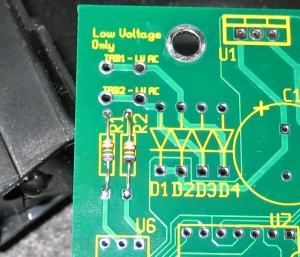
* Install two 750 ohm resistors R1 & R2. Make sure that the resistors have a value of 750 ohms [violet/green/brown/gold]. These resistors have no polarity to worry about. The body of the resistor can be a tan color (carbon film) or blue (metal film). These are simply different types of resistor construction. It does not matter which one is used in this application. | * Install two 750 ohm resistors R1 & R2. Make sure that the resistors have a value of 750 ohms [violet/green/brown/gold]. These resistors have no polarity to worry about. The body of the resistor can be a tan color (carbon film) or blue (metal film). These are simply different types of resistor construction. It does not matter which one is used in this application. Bend the resistor leads down so that a rough "U" shaped is formed. Insert the leads into the PCB and then bend the leads out slightly from the underside of the PCB. This allows the resistor to stay fixed while soldering the leads. Solder one lead and then check to make sure that the resistor did not "slide" out or otherwise move. If it did, then re-heat that joint and reposition the resistor. Once satisfied with the placement/alignment, solder the other lead and trim the excess lead. | ||
|| [[Image:Renard 64XC R1-R2 Install.jpg | 300px]] | |||
|- | |- | ||
| | | | ||
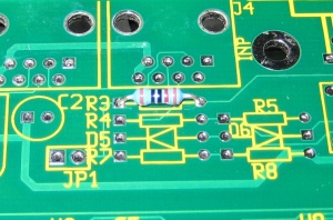
* Install the 120 ohm resistor R3. Make sure that the resistor has a value of 120 ohms [brown/red/brown/gold]. This resistor have no polarity to worry about. | * Install the 120 ohm resistor R3. Make sure that the resistor has a value of 120 ohms [brown/red/brown/gold]. This resistor have no polarity to worry about. | ||
|| [[Image:Renard 64XC R3 Install.jpg | 300px]] | |||
|- | |- | ||
| | | | ||
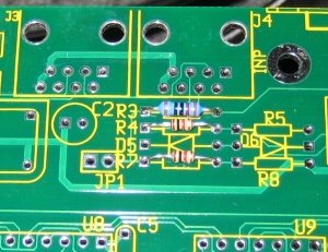
* Install two (2) 1K ohm resistors R4 and R7. Make sure that the resistors have a value of 1K ohm [brown/black/red/gold]. | * Install two (2) 1K ohm resistors R4 and R7. Make sure that the resistors have a value of 1K ohm [brown/black/red/gold]. | ||
|| [[Image:Renard 64XC R4-R7 Install.jpg | 300px]] | |||
|- | |- | ||
| | | | ||
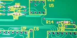
* Install three (3) 27K ohm resistors R5, R8, and R14. Make sure that the resistors have a value of 27K ohms [red/violet/orange/gold]. | * Install three (3) 27K ohm resistors R5, R8, and R14. Make sure that the resistors have a value of 27K ohms [red/violet/orange/gold]. | ||
|| [[Image:Renard 64XC R5-R8-R14 Install.jpg | 300px]] | |||
|- | |- | ||
| | | | ||
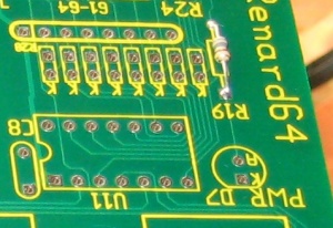
* Install one (1) 330 ohm | * Install one (1) 330 ohm resistor R19. Make sure that the resistors have a value of 330 ohms [orange/orange/brown/gold]. | ||
|| [[Image:Renard 64XC R19 Install.jpg | 300px]] | |||
|- | |- | ||
| | | | ||
* Install | * Install the eight (8) 680 ohm resistors R15-18 & R24-27. Make sure that the resistors have a value of 680 ohms [blue/gray/brown/gold]. | ||
|| [[Image:Renard 64XC R15-18 R24-27 Install.jpg | 300px]] | |||
|- | |- | ||
| | | | ||
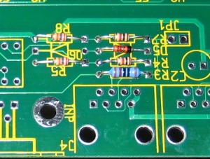
* Install zener diode D5. The diode must be installed correctly. The diode should have a black stripe on the orange/red body. Make sure that this stripe lines up with the stripe on the PCB silkscreen. | * Install 4.3v zener diode D5. The diode must be installed correctly. The diode should have a black stripe on the orange/red body. Make sure that this stripe lines up with the stripe on the PCB silkscreen. | ||
|| [[Image:Renard 64XC D5 Install.jpg | 300px]] | |||
|- | |- | ||
| | | | ||
* Install zener diode D6. The diode must be installed correctly. The diode should have a black stripe on the orange/red body. Make sure that this stripe lines up with the stripe on the PCB silkscreen. | * Install 9.1v zener diode D6. The diode must be installed correctly. The diode should have a black stripe on the orange/red body. Make sure that this stripe lines up with the stripe on the PCB silkscreen. | ||
|| [[Image:Renard 64XC D6 Install.jpg | 300px]] | |||
|- | |||
| | |||
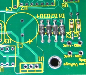
* Install four diodes D1 thru D4. The diodes will have a silver/grey stripe on a black body. Make sure that this stripe lines up with the stripe on the PCB silk screen. The diodes should be formed like the resistors above. Insert them into the holes and bend back the leads slightly to hold them in place. Solder and trim the leads like the resistors. | |||
|| [[Image:Renard 64XC D1-D4 Install.jpg | 300px]] | |||
|- | |||
!colspan="2"|<center>'''INSTALLATION NOTE:''' </center> | |||
<blockquote>The next few items are all very close to the same height. If in doubt which one is right, compare the components and change the order as appropriate. The order here follows the pictures and the specific components used. Part substitutions can affect this as well so if in doubt, check.</blockquote> | |||
<blockquote>Also, for the sockets, Pin 1 must be aligned with the square solder pad. Another way to verify that you installed them correctly is to make sure that the notch on the socket is aligned with the notch on the PCB silkscreen outline. </blockquote> | |||
|- | |- | ||
| | | | ||
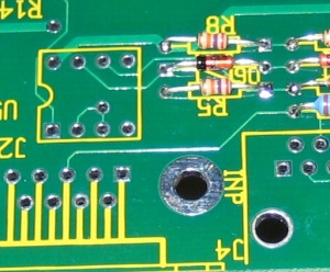
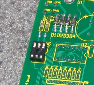
* Install | * Install one (1) 6-pin IC socket for U6. This part is not included in the original Renard 64XC BOM. However, it is strongly suggested that you use sockets for this IC chip so it is included in the latest BOM. Insert the socket as per the silkscreen. Solder pin #1 and check the component for "slippage". Once the component placement is confirmed, solder the other 5 pins. This item does not require trimming. Please note that the picture has the socket backwards. This can happen to the best of assemblers. It does not REQUIRE removal and repositioning as long as the chip is installed in the correct orientation. The best solution is to mark the socket with a dot of color (fingernail polish works well) on the socket as a reminder to check the chip placement. | ||
|| [[Image:Renard 64XC U6 Socket Install.jpg | 300px]] | |||
|- | |- | ||
| | | | ||
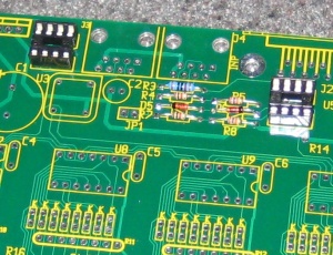
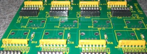
* Install two (2) 8-pin IC sockets for U4 & U5. These parts are not included in the original Renard 64XC BOM. However, it is strongly suggested that you use sockets for these IC chips so they are included in the latest BOM. Insert the sockets as per the silkscreen. Solder pin #1 and check the component for "slippage". Once the component placement is confirmed, solder the other 7 pins for each socket. These items do not require trimming. | |||
|| [[Image:Renard 64XC U4-U5 Socket Install.jpg | 300px]] | |||
|- | |- | ||
| | | | ||
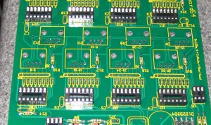
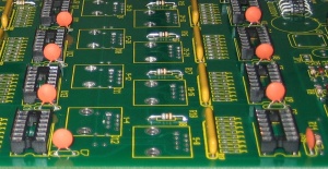
* Install | * Install eight (8) 14-pin IC sockets for U7-U14. Insert the sockets as per the silkscreen. Solder pin #1 and check the component for "slippage". Once the component placement is confirmed, solder the other 13 pins for each socket. These items do not require trimming. | ||
|| [[Image:Renard 64XC U4-U14 Socket Install.jpg | 300px]] | |||
|- | |- | ||
| | !colspan="2"|<center>'''INSTALLATION NOTE:''' </center> | ||
<blockquote>The following resistor network is a "bussed" type resistor network. This means that the seven (7) resistor components (pins 2-8) are all connected in a common buss to pin 1. Installing the resistor network backwards will cause a multitude of malfunctions. So please take the time to make sure they are installed correctly.</blockquote> | |||
|- | |- | ||
| | | | ||
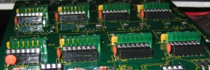
* Install | * Install the eight (8) 680 ohm resistor networks R10-R13 and R20-R23. The resistor network should have a dot on it to indicate pin 1. Insert pin 1 of the resistor network into the square solder pad. Sometimes a piece of tape is used to hold the resistor network in place while soldering the first pin. Once this is done, check the resistor network to ensure that it is straight and plumb to the board. If not, re-heat the first lead and reposition as required. Then, solder the other 7 pins. The leads do not have to be trimmed for this component. | ||
|| [[Image:Renard 64XC R10-R13 R20-R23 Socket Install.jpg | 300px]] | |||
|- | |- | ||
| | | | ||
* Install | * Install eight (8) 0.1uF capacitors C3-C10. These capacitors are not polarized so the orientation is not critical. The capacitor leads are already formed. However, sometimes they do not match the PCB holes exactly. Bend the leads as required to insert them into the PCB holes. Then, bend the leads back slightly to hold the capacitor in place. Solder and trim the leads the same as the resistors. | ||
|| [[Image:Renard 64XC C3-C10 Install.jpg | 300px]] | |||
|- | |- | ||
| | | | ||
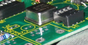
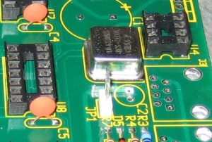
* Install the clock oscillator U3. The oscillator must be installed in the correct orientation. The oscillator has three rounded corners and one squared corner. Make sure that the squared corner is positioned to match the PCB silkscreen. | * Install the clock oscillator U3. The oscillator must be installed in the correct orientation. The oscillator has three rounded corners and one squared corner. Make sure that the squared corner is positioned to match the PCB silkscreen. Solder Pin #1, and then verify that the component placement matches the silkscreen and that the component has not "slipped" out of the hole. Once verified, solder the the remaining pins. Trim the excess leads as you would with a resistor or diode. | ||
|| [[Image:Renard 64XC U3 Install.jpg | 300px]] | |||
|- | |- | ||
| | | | ||
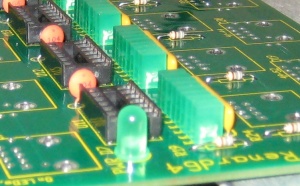
* Install | * Install sixty four (64) Green Channel LEDs. The LEDs are polarized and must be installed correctly. The long lead is the anode and must be placed in the square solder pad. The short lead is the cathode and this is marked on the silkscreen with a "K". Now, the question seems to come up a lot.."how do I get these straight?". Since the LEDs are rectangular, it is VERY noticeable if they are not. The best answer is to put them into the board and bend the leads back slightly as you would do for any other passive component. Then, put a piece of tape across the LEDs to hold them in place. Solder one lead on each LED and remove the tape. Now, you can reheat each single LED lead and make adjustments to line them up. Once you are satisfied, solder the other lead and trim the excess. The bottom edge of these rectangular LEDs is not smooth or uniform. So, if you want "perfect" alignment, be prepared to "lift" a few of the LEDs a bit to get them flush with their neighbors. | ||
|| [[Image:Renard 64XC Channel LED Install.jpg | 300px]] | |||
|- | |- | ||
| | | | ||
* | * Install the Power LED, D7. The LEDs are polarized and must be installed with the proper orientation. The long lead is the anode and must be placed in the round solder pad that is marked with an "A". The flat side of the LED (the short lead side) goes in the square pad marked with a "K". This is exactly opposite of the Channel LEDs in the previous step! Bend back the leads slightly as done with the resistors. Solder one lead and check from proper alignment. Then, solder the other lead and trim off the excess. | ||
|| [[Image:Renard 64XC Power LED D7 Install.jpg | 300px]] | |||
|- | |- | ||
| | | | ||
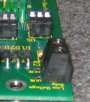
* | * The original Renard 64XC BOM calls for spades here. However, many users prefer to use a single 2 position terminal here. Install one (1) two position terminal block for 6.3VAC input. | ||
|| [[Image:Renard 64XC Terminal Install.jpg | 300px]] | |||
|- | |- | ||
| | | | ||
* | * Install one (1) 2-pin vertical header JP1. These headers are not polarized so the orientation is not important. Once again, a small piece of tape works well to hold the header in place. Solder one lead, check for alignment, then solder the opposite lead. No trimming is required for this component. | ||
|| [[Image:Renard 64XC JP1 Install.jpg | 300px]] | |||
|- | |- | ||
| | | | ||
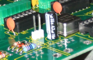
* Install | * Install the 47uF capacitor C2. This capacitor is polarized and must be installed correctly. The capacitor should have a silver/grey stripe on the body to indicate which lead is negative. The positive lead of the capacitor will be the longer lead. Make sure that the positive lead is placed in the square solder pad. Then, bend the leads back slightly to hold the capacitor in place. Solder and trim the leads the same as the other passives. | ||
|| [[Image:Renard 64XC C2 Install.jpg | 300px]] | |||
|- | |- | ||
| | | | ||
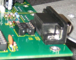
* OPTIONAL: | * OPTIONAL: Install the DE9 connector J22. This connector is only needed if you plan on using a normal serial cable to connect to the first board in the chain. You can, however, make a DE9 x RJ45 cable instead. For boards after the first one on the PC COMM port, this connector is not needed. | ||
|| [[Image:Renard 64XC J22 Install.jpg | 300px]] | |||
|- | |- | ||
| | | | ||
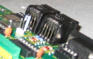
* Install two (2) RJ45 modular jacks J3 and J4. Due to minor variations in manufacturing, some RJ45 jacks are a tighter fit than others. Care should be taken to ensure that the pins are aligned first before applying too much pressure to seat the locking lugs through the board. | * Install two (2) RJ45 modular jacks J3 and J4. Due to minor variations in manufacturing, some RJ45 jacks are a tighter fit than others. Care should be taken to ensure that the pins are aligned first before applying too much pressure to seat the locking lugs through the board. | ||
|| [[Image:Renard 64XC J3-J4 Install.jpg | 300px]] | |||
|- | |- | ||
| | | | ||
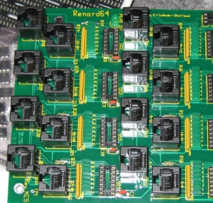
* Install sixteen (16) RJ45 Top Entry modular jacks J5-J16 and J18-J21. Due to minor variations in manufacturing, some RJ45 jacks are a tighter fit than others. Care should be taken to ensure that the pins are aligned first before applying too much pressure to seat the locking lugs through the board. | * Install sixteen (16) RJ45 Top Entry modular jacks J5-J16 and J18-J21. Due to minor variations in manufacturing, some RJ45 jacks are a tighter fit than others. Care should be taken to ensure that the pins are aligned first before applying too much pressure to seat the locking lugs through the board. | ||
|| [[Image:Renard 64XC J5-J16 J18-J21 Install.jpg | 300px]] | |||
|- | |||
| | |||
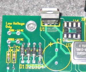
* Install the voltage regulator U1. The voltage regulator must be installed correctly. The voltage regulator's tab/heat sink must be aligned with wider line of the PCB silkscreen outline (facing outwards to the PCB edge). Insert the component and then flip the board over. Solder one pin...then flip the board back over and check for alignment. Simply reheat the joint and position the regulator so that it is square to the board. Solder the other two leads and trim off the excess. | |||
|| [[Image:Renard 64XC U1 Install.jpg| 300px]] | |||
|- | |- | ||
| | | | ||
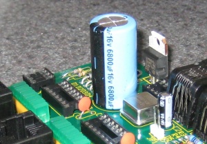
* | * Install the 6800uF capacitor C1. This capacitor is polarized and must be installed correctly. The capacitor should have a black stripe on the body to indicate the negative lead. The positive lead of the capacitor will be the longer lead. Make sure that the positive lead is placed in the square solder pad. Then, bend the leads back slightly to hold the capacitor in place. Solder and trim the leads the same as the other passives. | ||
|| [[Image:Renard 64XC C1 Install.jpg| 300px]] | |||
|- | |- | ||
!colspan="2" |<blockquote> If you are unsure about your ability to build this board, then you should go to [[Beginners_Setup_Guide_Renard_Boards_with_External_SSR | The Beginner's Setup Guide]] at this point. [[Beginners_Setup_Guide_Renard_Boards_with_External_SSR | The Beginner's Setup Guide]] will walk you thru some initial tests to make sure that everything is working correctly before inserting the IC chips. </blockquote> | |||
|- | |- | ||
|<center>'''INSTALLATION NOTE:''' </center> | !colspan="2"|<center>'''INSTALLATION NOTE:''' </center> | ||
<blockquote>Pin 1 of each IC must be aligned with pin 1 of the corresponding socket. This can be verified by noting that the notch on the IC is aligned with the notch on the socket. | <blockquote>Pin 1 of each IC must be aligned with pin 1 of the corresponding socket. This can be verified by noting that the notch on the IC is aligned with the notch on the socket. | ||
|- | |- | ||
| | | | ||
* Install the H11AA1 optocoupler | * Install the H11AA1 optocoupler U6. | ||
|- | |- | ||
| | | | ||
* Install eight (8) PIC microcontrollers U7-U14. The PICs need to be programmed with the appropriate firmware before installation. More info on programming PICs can be found [http://www.doityourselfchristmas.com/forums/showpost.php?p=3346&postcount=1 here.] | * Install eight (8) PIC microcontrollers U7-U14. The PICs need to be programmed with the appropriate firmware before installation. More info on programming PICs can be found [http://www.doityourselfchristmas.com/forums/showpost.php?p=3346&postcount=1 here.] | ||
|- | |- | ||
| | | | ||
* Install two (2) RS232/RS485 Interface ICs U4 & U5. | * Install two (2) RS232/RS485 Interface ICs U4 & U5. | ||
|- | |- | ||
| | | | ||
* OPTIONAL: Install a heat sink (PN# 532-577102B00) on voltage regulator U1. The mounting hardware and heat transfer compound are not included in the BOM since any common hardware can be used to attach the heat sink. If you don't have any heat transfer compound handy, you can use Mouser PN# 532-249. | * OPTIONAL: Install a heat sink (PN# 532-577102B00) on voltage regulator U1. The mounting hardware and heat transfer compound are not included in the BOM since any common hardware can be used to attach the heat sink. If you don't have any heat transfer compound handy, you can use Mouser PN# 532-249. | ||
|- | |- | ||
|} | |} | ||
| Line 138: | Line 152: | ||
<! | <center>'''Congratulations! You have finished building your Renard 64!'''</center> | ||
[[Category:Renard 64XC]] | |||
[[Category:DIYC Index]] | |||
Latest revision as of 03:59, 2 October 2012
Board Assembly
- Note: Pictures are being added daily and the sequence is changing based on an actual assembly.
- The following sequence of steps is by no means the only way to assemble the Renard 64. It is simply a suggested order of assembly. Many builders have varied opinions on what the order should be. In general, you start with the "shortest" items and work towards the tallest. This generally means that resistors are first and connectors are last but every board is different.
- A good temperature controlled soldering iron should be used for building the Renard 64. Try to get the smallest diameter rosin core solder you can find (either 60/40 or 63/37). PLEASE DO NOT USE LEAD FREE SOLDER!! This takes special equipment and a very high skill set that few DIYers have. If you do use Lead Free Solder and have problems (which is VERY likely) please let us know when you ask for help. Lead Free Solder can look like a good joint but still be a problem.
- One safety note is prudent here. Solder is METAL (lead and tin)...In order to use it,it must be MELTED. HOT, Molten Metal can BURN! Also, metal leads get hot while soldering. So, any unprotected fingers that are being used to "hold" a component in place will be burned!! Painter's tape is one way of holding items down while the board is being flipped over. Another way is to use another unpopulated board or flat surface to allow the board to be flipped while keeping the components in place.
- NOTE: The part numbers referenced in the following instructions are those taken from the Renard 64 BOM.
| |
|
|
|
|
|
|
|
|
|
|
|
|
|
|
|
|
|
|
| |
|
|
|
|
|
|
| |
|
|
|
|
|
|
|
|
|
|
|
|
|
|
|
|
|
|
|
|
|
|
|
|
|
|
| |
| |
| |
| |
| |
| |